DIVING REGULATOR

A diving regulator is a pressure regulator used in scuba or surface supplied diving equipment that reduces pressurized breathing gas to ambient pressure and delivers it to the diver. The gas may be air or one of a variety of specially blended breathing gases. The gas may be supplied from a cylinder worn by the diver (as in a scuba set), or via a hose from a compressor or a bank of cylinders on the surface (as in surface-supplied diving). A gas pressure regulator has one or more valves in series, which reduces pressure from the source in a controlled manner, lowering pressure at each stage.
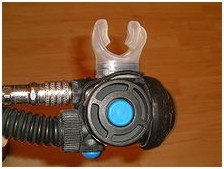
The terms “regulator” and “demand valve” are often used interchangeably, but a demand valve is the part of a regulator that delivers gas only while the diver is breathing in and reduces the gas pressure to ambient. In single hose regulators, it is part of the second stage held in the diver’s mouth by a mouthpiece. In double hose regulators it is part of the regulator attached to the cylinder.
Types of diving regulator
Demand valve
A demand valve detects when the diver starts inhaling and supplies the diver with a breath of gas at ambient pressure.
The demand valve was invented in 1838 in France,and forgotten in the next few years; another workable demand valve was not invented until 1860.
- On November 14, 1838, Dr. Manuel Théodore Guillaumet of Argentan, Normandy, France, filed a patent for a twinhose demand regulator; the diver was provided air through pipes from the surface. The apparatus was demonstrated to, and investigated by, a committee of the French Academy of Sciences: “Mèchanique appliquée — Rapport sur une cloche à plongeur inventée par M. Guillaumet” (Applied mechanics — Report on a diving bell invented by Mr. Guillaumet), Comptes rendus, vol. 9, pages 363-366 (September 16, 1839).
- Illustration of diving apparatus invented by Dr. Manuel Théodore Guillaumet from: Alain Perrier, 250 Réponses aux questions du plongeur curieux [250 Answers to the questions of the curious diver] (Aix-en-Provence, France: Éditions du Gerfaut, 2008), page 45.
- On June 19, 1838, in London, England, a Mr. William Edward Newton first filed a patent (no. 7695: “Diving apparatus”) for a diaphram-actuated, twin-hose demand valve for divers. (See: John Bevan (1990) “The First Demand Valve?,” SPUMS Journal [SPUMS = South Pacific Underwater Medicine Society], vol. 20, no. 4, pages 239-240.) However, it is believed that Mr. Newton was merely filing a patent on behalf of Dr. Guillaumet. (See: le scaphandre autonome (scuba diving): Un brevet semblable est déposé en 1838 par William Newton en Angleterre. Il y a tout lieu de penser que Guillaumet, devant les longs délais de dépôt des brevets en France, a demandé à Newton de faire enregistrer son brevet en Angleterre où la procédure est plus rapide, tout en s’assurant les droits exclusifs d’exploitation sur le brevet déposé par Newton. (A similar patent was filed in 1838 by William Newton in England. There is every reason to think that owing to the long delays in filing patents in France, Guillaumet asked Newton to register his patent in England where the procedure was faster, while ensuring the exclusive rights to exploit the patent filed by Newton. [Note: The illustration of the apparatus in Newton’s patent application is identical to that in Guillaumet’s patent application; furthermore, Mr. Newton was apparently an employee of the British Office for Patents, who applied for patents on behalf of foreign applicants.]
Also from “le scaphandre autonome” Web site: Reconstruit au XXe siècle par les Américains, ce détendeur fonctionne parfaitement, mais, si sa réalisation fut sans doute effective au XIXe, les essais programmés par la Marine Nationale ne furent jamais réalisés et l’appareil jamais commercialisé. (Reconstructed in twentieth century by the Americans, this regulator worked perfectly; however, although it was undoubtedly effective in the nineteenth century, the test programs by the French Navy were never conducted and the apparatus was never sold.))
In 1860 a mining engineer from Espalion (France), Benoît Rouquayrol, had invented a demand valve with an iron air reservoir to let miners breathe in flooded mines. He called his invention régulateur (‘regulator’).
In 1864 Rouquayol met the French Imperial Navy officer Auguste Denayrouze and both worked together to adapt Rouquayrol’s regulator to diving. The Rouquayrol-Denayrouze apparatus was mass produced, though with some interruptions, from 1864 to 1965.
As of 1865 it was acquired as a standard by the French Imperial Navy but never was entirely accepted by the French divers because of a lack of safety and autonomy.
In 1926 Maurice Fernez and Yves Le Prieur patented a hand-controlled regulator (not a demand valve then) which used a full-face mask (the air escaping from the mask at constant flow).
It was not until December 1942 that the demand valve was definitely improved in the way we know nowadays, when Frenchmen Jacques-Yves Cousteau (navy officer) and Émile Gagnan (engineer) met for the first time in Paris. Gagnan, employee at Air Liquide, had miniaturized and adapted a Rouquayrol-Denayrouze regulator to gas generators (following severe fuel restrictions due to the German occupation of France) and Cousteau suggested to adapt it again to diving, which was in 1864 its original purpose. Smaller than the large Rouquayrol-Denayrouze regulator and equipped with a safer reservoir (three gas cylinders at the time) the modern demand valve was born. Another French inventor, Georges Commeinhes from Alsace, had patented in 1937 and 1942 a diving demand valve, air-supplied by two gas cylinders through a full-face mask. Commeinhes died in 1944 during the liberation of Strasbourg and his invention was soon forgotten. In any case the Commeinhes demand valve was also an adaptation of the Rouquayoul-Denayrouze mechanism, but not as precise and miniaturized as was the Cousteau-Gagnan apparatus.
The demand valve has a chamber, which in normal use contains breathing gas at ambient pressure. A valve which supplies medium pressure gas can vent into the chamber. Either a mouthpiece or a full-face mask is connected to the chamber, for the diver to breathe from. On one side of the chamber is a flexible diaphragm to control the operation of the valve.
Modern demand valves use both breathing systems, mouthpiece or full-face mask, depending on the purpose of the dive. Modern full-face masks, for example, allow the use of underwater communication systems (usually called intercoms). Historically old demand valves also used one or the other system: the 1838 Guillaumet, 1864 Rouquayrol-Denayrouze, 1926 Fernez-Le Prieur and 1943 Cousteau-Gagnan apparati used all of them mouthpieces to provide the air to the diver (although the 1838 Guillaumet’s demand valve wasn’t independent from the surface and the Fernez-Le Prieur patent wasn’t a demand valve). The 1933 Le Prieur and 1942 Commeinhes apparati used full-face masks.
When the diver starts to breathe in, the inhalation lowers the pressure inside the chamber, which moves the diaphragm inwards operating a system of levers. This operates against the closing spring and lifts the valve off its seat, opening the valve and releasing gas into the chamber. The medium pressure gas, at about 10 bar/140 psi over ambient pressure, expands, reducing its pressure to ambient pressure, blowing out any water in the chamber and supplying the diver with gas to breathe. When the chamber is full and the lowering of pressure has been reversed, the diaphragm expands outwards to its normal position to close the medium pressure valve when the diver stops breathing in.
When the diver exhales, one-way valves, made from a flexible and air-tight material, flex outwards under the pressure of the exhalation allowing gas to escape from the chamber. They close making a seal when the exhalation stops and the pressure inside the chamber reduces to ambient pressure.
The diaphragm is protected by a cover, which the outside water can enter freely through holes or slits.
Demand valves can be of both the open circuit or reclaim types. The vast majority of demand valves are open circuit, which means that the exhaled gas is discharged into the surrounding environment and lost. Reclaim systems allow the used gas to be returned to the surface or (more often) diving bell for re-use after removing the carbon dioxide and making up the oxygen. This process, referred to as “push-pull” is technologically complex and expensive, and is only used for deep commercial diving on heliox mixtures, as the saving on helium compensates for the expense and complications of the system.
Free-flow regulator
These are generally used in surface supply diving with free-flow masks and helmets, and are usually simply a large high flow rated industrial gas regulator, which is manually controlled at the gas panel on the surface to the pressure required to provide to desired flow rate to the diver. Free flow is not normally used on scuba equipment as the high gas flow rates are inefficient and wasteful.
Rebreather regulators
The scuba rebreather systems also recycle the breathing gas, but are not based on a demand valve system for their primary function, as the breathing loop is carried by the diver and remains at ambient pressure while in use. Regulators used in scuba rebreathers are described below.
Automatic diluent valve (ADV)
These are used in rebreathers to add gas to the loop to compensate automatically for volume reduction due to pressure increase with greater depth, or to make up gas lost from the system by the diver exhaling through the nose while clearing the mask or as a method of flushing the loop. They are often provided with a purge button to allow manual flushing of the loop. The ADV is virtually identical in function to the open circuit demand valve.
Bailout valve (BOV)
This is an open circuit demand valve built into a rebreather mouthpiece, or other part of the breathing loop, which can be isolated while the diver is using the rebreather to recycle breathing gas, and opened at the same time as isolating the breathing loop when a problem causes the diver to bail out onto open circuit. The main distinguishing feature of the BOV is that the same mouthpiece is used for open and closed circuit, and the diver does not have to shut the Dive/Surface valve, remove it from his/her mouth, and find and insert the bailout demand valve in order to bail out onto open circuit. This reduction in critical steps makes the integrated BOV a significant safety advantage, though they are costly.
Constant mass flow addition valve
These are used to supply a constant mass flow of fresh gas to an active type semi-closed rebreather, to replenish the gas used by the diver and to maintain an approximately constant composition of the loop mix. Two main types are used: the fixed orifice and the adjustable orifice, usually a needle valve. The constant mass flow valve is usually based on a gas regulator which is isolated from the ambient pressure so that it provides an absolute pressure regulated output (not compensated for ambient pressure). This limits the depth range in which constant mass flow is possible through the orifice, but provides a relatively predictable gas mixture in the breathing loop. An overpressure valve is used to protect the output hose.
Manual and electronically controlled addition valves
These are used on manual and electronically controlled closed circuit rebreathers (mCCR, eCCR), to add oxygen to the loop to maintain set-point. A manually or electronically controlled valve is used to release oxygen from the outlet of a standard scuba regulator first stage into the breathing loop. An overpressure valve is necessary to protect the hose (see below)
Structure and function of diving regulators

A diving regulator A-clamp type first stage

A DIN fitting stage with 2 medium pressure and 1 high pressure hose
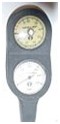
A depth gauge and standard contents gauge

A button contents gauge on an ‘A’ clamp type first stage
A 1960s era Sportsways “Waterlung” Regulator with “J” Valve incorporated
The parts of a regulator are described as the major functional groups in downstream order as following the gas flow from the cylinder to its final use, and accessories which are not part of the primary functional components, but are commonly found on contemporary regulators. Some historically interesting models and components are described in a later section.
Single hose two-stage open circuit demand regulators
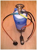
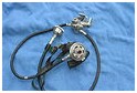
A “single-hose” aqualung with the first stage on top of the cylinder and the second stage demand valve on the left hand hose
Most contemporary diving regulators are single hose two-stage regulators. They consist of a first stage regulator, and a second stage demand valve. An intermediate pressure hose connects these components to transfer air, and allows relative movement within the constraints of hose length and flexibility. Other medium pressure hoses run to various equipment listed below.
The first make of this sort of scuba was the Porpoise which was made in Australia and was invented by Ted Eldred. At the same time in France, the Cristal Explorer (single hose) was designed by Bronnec & Gauthier.
The first stage
The first stage of the regulator is mounted to the cylinder valve via one of the standard connectors. It reduces cylinder pressure to a middle or intermediate pressure, usually about 10 bars (150 psi) higher than the ambient pressure. The breathing gas then passes through a hose to the second stage.
A balanced regulator first stage automatically keeps a constant pressure difference between the interstage pressure and the ambient pressure even as the tank pressure drops with consumption. The balanced regulator design allows the first stage orifice to be as large as needed without incurring performance degradation as a result of changing tank pressure.
The first stage generally has several low-pressure outlets (ports) for second-stage regulators, BCD inflators and other equipment; and one or more high-pressure outlets, which allow a submersible pressure gauge (SPG) or gas-integrated diving computer to read the cylinder pressure. The valve may be designed so that one low-pressure port is designated “Reg” for the primary second stage regulator, because that port allows a higher flow rate to give less breathing effort at maximum demand. A small number of manufacturers have produced regulators with a larger than standard hose and port diameter for this primary outlet.
Types of first stage

Diagram of the internal components of a balanced piston-type first stage
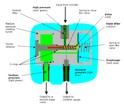
Diagram of the internal components of a diaphragm-type first stage
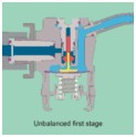
Diagram of the internal components of an unbalanced diaphragm first stage
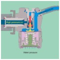
Diagram of the internal components of a balanced diaphragm first stage
Animation of the internal components of a diaphragm-type first stage during the breathing cycle
The mechanism inside the first stage can be of the diaphragm type or the piston type. Both types can be balanced or unbalanced. Unbalanced regulators have the cylinder pressure pushing the first stage upstream valve closed, which is opposed by the intermediate stage pressure and a spring. As cylinder pressure falls the closing force is less, so the regulated pressure increases at lower tank pressure. To keep this pressure rise within acceptable limits the high-pressure orifice size was limited, but this decreased the total flow capacity of the regulator. A balanced regulator keeps about the same ease of breathing at all depths and pressures, by using the cylinder pressure to also indirectly oppose the opening of the first stage valve.
Piston type first stage
Some components of piston-type first stages are easier to manufacturer and have a simpler design than the diaphragm type. They need more careful maintenance because some internal moving parts are exposed to water and any contaminants in the water.
The piston in the first stage is rigid and acts directly on the seat of the valve. The pressure in the medium (aka intermediate) pressure chamber drops when the diver inhales from the second stage valve, this causes the piston to lift off the stationary valve seat as the piston slides into the intermediate pressure chamber. The now open valve permits high pressure gas to flow into the medium pressure chamber until the pressure in the chamber has risen enough to push the piston back into its original position against the seat and thus close the valve.
Diaphragm type first stage
Diaphragm-type first stages are more complex and have more components than the piston type. This design means that they are particularly suited to cold water diving and to working in saltwater and water containing a high degree of suspended particles, silt, or other contaminating materials, since the only parts exposed to the water are the valve opening spring and the diaphragm, all other parts are sealed off from the environment. In some cases the diaphragm and spring are also sealed from the environment.
The diaphragm is a flexible cover to the medium (intermediate) pressure chamber. When the diver consumes gas from the second stage, the pressure falls in the medium pressure chamber and the diaphragm deforms inwards pushing against the valve lifter. This opens the high pressure valve permitting gas to flow past the valve seat into the medium-pressure chamber. When the diver stops inhaling, pressure in the medium pressure chambers rises and the diaphragm returns to its neutral flat position and no longer presses on the valve lifter shutting off the flow until the next breath is taken.
Connection of first stage regulator to the cylinder valve or cylinder manifold
In an open-circuit scuba set, the first-stage of the regulator has an A-clamp, also known as a “yoke” or “international” connection, or a DIN fitting to connect it to the pillar valve of the diving cylinder. There are also European standards for scuba regulator connectors for gases other than air.
Yoke valves are the most popular in North America and many countries with large numbers of recreational diving tourists; it clamps an open hole on the regulator against an open hole on the cylinder. The user screws the clamp in place finger-tight, and once the cylinder valve is opened, gas pressure completes the seal along with an O-ring. The diver must take care not to screw the yoke down too tightly, or it may prove impossible to remove without tools. Conversely, failing to tighten sufficiently can lead to O-ring extrusion and a loss of cylinder gas, which can be a serious problem if it happens when the diver is at depth. Yoke fittings are rated up to a maximum of 240 bar working pressure.
The DIN fitting is a type of direct screw-in connection to the cylinder. While less common worldwide, the DIN system has the advantage of withstanding greater pressure, up to 300 bar, permitting the use of high-pressure steel cylinders. They are also less susceptible to blowing the O-ring seal if banged against something. DIN fittings are the standard in much of central Europe and are available in most countries. The DIN fitting is considered more secure and therefore safer by many Technical divers.
Adapters are available enabling a DIN first-stage to be attached to a cylinder with a yoke fitting valve, and for a Yoke first stage to be attached to a DIN cylinder valve.
Most cylinder valves are currently of the K-valve type, which is a simple manually operated screw-down on-off valve. In the mid-1960s, J-valves were widespread. J-valves contain a spring-operated valve that is restricts or shuts off flow when tank pressure falls to 300-500 psi, causing breathing resistance and warning the diver that he or she is dangerously low on air. The reserve air is released by pulling a reserve lever on the valve. J-valves fell out of favor with the introduction of pressure gauges, which allow divers to keep track of their air underwater, especially as the valve-type is vulnerable to accidental release of reserve air and increases the cost and servicing of the valve. J-valves are occasionally still used when work is done in visibility so poor that the pressure gauge cannot be seen, even with a light.
Risk of the regulator becoming blocked with ice
As gas leaves the cylinder it decreases in pressure in the first stage, becoming very cold due to adiabatic expansion. Where the ambient water temperature is less than 5°C any water in contact with the regulator may freeze. If this ice jams the diaphragm or piston spring, preventing the valve closing, a free-flow may ensue that can empty a full cylinder within a minute or two, and the free-flow causes further cooling in a positive feedback loop. Generally the water that freezes is in the ambient pressure chamber around a spring that keeps the valve open and not moisture in the breathing gas from the cylinder, but that is also possible if the air is not adequately filtered.
The modern trend of using more plastics, instead of metals, within the regulators encourages freezing because it insulates the inside of a cold regulator from the warmer surrounding water.
Cold water kits can be used to reduce the risk of freezing inside the regulator. Some regulators come with this as standard, and some others can be retrofitted. Environmental sealing of the diaphragm main spring chamber using a soft secondary diaphragm and hydrostatic transmitter or a silicone, alcohol or glycol/water mixture antifreeze liquid in the sealed spring compartment can be used for a diaphragm regulator. Silicone grease in the spring chamber can be used on a piston first stage.
The Poseidon Xstream first stage insulates the external spring and spring housing from the rest of the regulator, so that it is less chilled by the expanding air, and provides large slots in the housing so that the spring can be warmed by the water, thus avoiding the problem of freezing up the external spring.
Interstage hose
A medium (intermediate) pressure hose is used to allow breathing gas (typically at between 9 and 13 atmospheres above ambient) to flow from the first stage regulator to the second stage, or demand valve, which is held in the mouth by the diver, or attached to the full face mask or diving helmet.
Second stage or Demand valve
Types of second stage

A pair of demand valves

Animation of demand valve function during the breathing cycle

Air flow through the exhaust valve
Twin-hose open circuit demand scuba regulators
The “twin”, “double” or “two” hose type of scuba demand valve was the first in general use.
This type of regulator has two large bore corrugated breathing tubes. One tube is to supply air from the regulator to the mouthpiece, and the second tube is for exhalation; it is not for rebreathing but to keep the air inside the breathing tube at the same pressure as the water at the regulator diaphragm. This second breathing tube returns the exhaled air to the regulator on the wet side of the diaphragm, where it is released through a rubber duck-bill one-way valve, and comes out of the holes in the cover.
In Cousteau’s original aqualung prototype, there was no exhaust hose, and the exhaled air exited through a one-way valve at the mouthpiece. It worked out of water, but when he tested the aqualung in the river Marne air escaped from the regulator before it could be breathed when the mouthpiece was above the regulator. After that, he had the second breathing tube fitted.
Even with both tubes fitted, raising the mouthpiece above the regulator increases the flow of gas and lowering the mouthpiece increases breathing resistance. As a result, many aqualung divers, when they were snorkeling on the surface to save air while reaching the dive site, put the loop of hoses under an arm to avoid the mouthpiece floating up causing free flow.
Diver orientation changes breathing characteristic of regulators. With twin hose regulator on back at shoulder level, if the diver rolls on his or her back the released air pressure is higher than in the lungs. Divers learned to restrict flow by using their tongue to close the mouthpiece. When the cylinder pressure was running low and air demand effort rising, a roll to the right side made breathing easier.
Divers had to carry more weight underwater to compensate for the buoyancy of the air in the hoses. An advantage with this type of regulator is that the bubbles leave the regulator behind the diver’s head, increasing visibility, and not interfering with underwater photography. Twin hose regulators have been superseded by single hose regulators and became obsolete for most diving in the 1980s.
Some modern twin-hose regulators have one or more low-pressure ports that branch off between the two valve stages, which can be used to supply direct feeds for suit or BC inflation and/or a secondary single hose demand valve, and a high pressure port for a submersible pressure gauge.
Someone made a twin-hose type regulator where the energy released as the air expands from cylinder pressure to the surrounding pressure as the diver breathes in, is not thrown away but used to power a propeller.
The twin-hose arrangement with a mouthpiece or full-face mask has reappeared in modern rebreathers, but as part of the breathing loop, not as part of a regulator. The associated demand valve comprising the bail-out valve is always a single hose regulator.
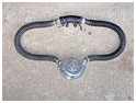
Old-style “twin-hose” twin cylinder aqualung

Nemrod twin-hose regulator made in the 1980s. It has one low-pressure port, which feeds the left (inhalation) hose. Its mouthpiece can be strapped in.
The Draeger two stage twin hose regulator
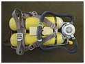
Twin 7l cylinders with Draeger harness, valves, manifold and regulator from c1965
Two stage twin hose open circuit demand regulators
Early open circuit scuba demand regulators were mostly twin hose designs. The mechanism of the regulator is packaged in a usually circular metal housing mounted on the cylinder valve behind the diver’s neck, and the air flows through a pair of corrugated rubber hoses to and from the mouthpiece. The supply hose is connected to one side of the regulator body and supplies air to the mouthpiece through a non-return valve, and the exhaled air is returned to the regulator housing on the outside of the diaphragm, also through a non-return valve on the other side of the mouthpiece, and usually through another non-return exhaust valve in the regulator housing, often a “duckbill” type. The demand valve component of a two stage twin hose regulator is thus mounted in the same housing as the first stage regulator, and in order to prevent free-flow, the exhaust valve is located at the same depth as the diaphragm, and the only reliable place to do this is in the same housing.
Single stage twin hose open circuit demand regulators
Beuchat “Souplair” single stage twin hose regulator
Some early twin hose regulators were of single stage design. The first stage functions in a way similar to the second stage of two-stage demand valves, but would be connected directly to the cylinder valve and reduced high pressure air from the cylinder directly to ambient pressure on demand. This could be done by using a longer lever and larger diameter diaphragm to control the valve movement, but there was a tendency for cracking pressure, and thus work of breathing, to vary as the cylinder pressure dropped.
Rebreather Automatic Diluent Valves
Some passive semi-closed circuit rebreathers use a form of demand valve, which senses the volume of the loop and injects more gas when the volume falls below a certain level.
Upstream vs downstream
Most modern demand valves use a downstream rather than an upstream valve mechanism. In a downstream valve, the moving part of the valve opens in the same direction as the flow of gas and is kept closed by a spring. In an upstream valve, the moving part works against the pressure and opens in the opposite direction as the flow of gas. If the first stage jams open and the medium pressure system over-pressurizes, the second stage downstream valve opens automatically resulting in a “freeflow”. With an upstream valve, the result of over-pressurization may be a blocked valve. This will stop the supply of breathing gas, and possibly result in a ruptured hose or the failure of another second stage valve, such as one that inflates a buoyancy device. When a second stage upstream tilt valve is used a relief valve should be included by the manufacture on the first stage regulator to protect the intermediate hose.
If a shut-off valve is fitted between the first and second stages, as is found on scuba bailout systems used for commercial diving, and in some technical diving configurations, the demand valve will normally be isolated and unable to function as a relief valve. In this case an overpressure valve must be fitted to the first stage if it does not already have one. As very few contemporary (2011) scuba regulator first stages are factory fitted with overpressure relief valves, they are available as aftermarket accessories which can be screwed into any low pressure port available on the first stage.
Regulator accessories
Pressure relief valve
A downstream demand valve serves as a fail safe for over-pressurization: if a first stage with a demand valve malfunctions and jams in the open position, the demand valve will be over-pressurized and will “free flow”. Although it presents the diver with an imminent “out of air” crisis, this failure mode lets gas escape directly into the water without inflating buoyancy devices. The effect of unintentional inflation might be to carry the diver quickly to the surface causing the various injuries that can result from an over-fast ascent. There are circumstances where regulators are connected to inflatable equipment such as a rebreather’s breathing bag, a buoyancy compensator or a drysuit but without the need for demand valves. Examples of this are argon suit inflation sets, and “off board” or secondary diluent cylinders for closed-circuit rebreathers. When no demand valve is connected to a regulator, it should be equipped with a pressure relief valve’, unless it has a built in over pressure valve, so that over-pressurization does not inflate any buoyancy devices connected to the regulator.
Submersible pressure gauge (SPG)
To monitor breathing gas pressure in the diving cylinder, a diving regulator usually has a high pressure hose leading to a contents gauge(also called pressure gauge). The port for this hose leaves the first-stage upstream of all pressure-reducing valves. The contents gaugeis a pressure gauge measuring the gas pressure in the diving cylinder so the diver knows how much gas remains in the cylinder. It is also known as submersible pressure gauge or SPG. There are several types of contents gauge:-
Standard type
This is an analogue gauge that can be held in the palm of a hand and is connected to the first stage by a high pressure hose. It displays with a pointer moving over a dial. Sometimes they are fixed in a console, which is a plastic or rubber case that holds the air pressure gauge and also a depth gauge and/or a dive computer and/or a compass.
Button gauges
These are coin-sized analogue pressure gauges located on the first stage. They are compact, have no dangling hoses and few points of failure. They are generally not used on back mounted cylinders, because the diver cannot easily see them there when underwater. They are sometimes used on side slung stage cylinders. Due to their small size, it can be difficult to read the gauge to a resolution of less than 20 bar / 300 psi.
Air integrated computers
Some dive computers are designed to measure, display, and monitor pressure in the diving cylinder. This can be very beneficial to the diver, but if the dive computer fails, the diver can no longer monitor his or her gas reserves. Most divers using a gas-integrated computer will also have a standard air pressure gauge. The computer is either connected to the first stage by a high pressure hose, or has two parts, the pressure transducer on the first stage and the display at the wrist or console, which communicate by radio link; the signals are encoded to eliminate the risk of one diver’s computer picking up a signal from another diver’s transducer, or radio interference from other sources.
Mechanical reserve valves
In the past, some types of diving cylinder had a mechanical reserve valve that restricted air flow when the pressure was below 500 psi. Alerted to having a low gas supply the diver would pull a lever to open the reserve valve and surface using the reserve gas. Occasionally, a diver would inadvertently trigger the mechanism while donning gear or performing a movement underwater and, unaware that the reserve had already been accessed, could find himself out of breathing gas with no warning. These valves are known as “J valves” due to the letter J being next to that valve in the US Divers product catalog. Valves without the reserve lever are called “K valves” for the same reason; being the next item in the catalog they were denoted by the letter K. Modern divers using “J valves” dive with the reserve valve in the open position and depend on a contents gauge or computer to monitor gas supply.
Secondary demand valve (Octopus)
A combined diving regulator demand valve and BC inflation valve
As a nearly universal standard practice in modern recreational diving, the typical single-hose regulator has a spare demand valve fitted for emergency use by the diver’s buddy, typically referred to as the octopus because of the extra hose, or secondary DV. The medium pressure hose on the octopus is usually longer than the medium pressure hose on the primary DV that the diver uses, and the demand valve and/or hose may be colored yellow to aid in locating during an emergency. The secondary regulator should be clipped to the diver’s harness in a position where it can be easily seen and reached by both the diver and the potential sharer of air. The longer hose is used for convenience when sharing air, so that the divers are not forced to stay in an awkward position relative to each other. Technical divers frequently extend this feature and use a 5′ or 7′ hose, which allows divers to swim in single file while sharing air, which may be necessary in restricted spaces inside wrecks or caves.
The secondary demand valve can be a hybrid DV and buoyancy compensator inflation valve. Both types are sometimes called alternate air sources. A DV on a regulator connected to a separate independent diving cylinder would also be called an “alternate air source”, and also a redundant air source, as it is totally independent of the primary air source.
Full face mask or helmet
This is stretching the concept of accessory a bit, as it would be equally valid to call the regulator an accessory of the full face mask or helmet, but the two items are closely connected, and generally found in use together.
Most full face masks and probably most diving helmets currently in use are open circuit demand systems, using a demand valve (in some cases more than one) and supplied from a scuba regulator and frequently also a surface supply umbilical from a surface supply panel using a surface supply regulator to control the pressure of primary and reserve air or other breathing gas.
Lightweight diving helmets are almost always surface supplied, but full face masks are used equally appropriately with scuba open circuit, scuba closed circuit (rebreathers) and surface supplied open circuit.
The demand valve is usually firmly attached to the helmet or mask, but there are a few models of full face mask which have removable demand valves with quick connections, allowing them to be exchanged under water. These include the Draeger Panorama and Kirby-Morgan 48 Supermask.
Buoyancy compensator and dry suit inflation hoses

A drysuit direct feed a.k.a. a power inflator. CEJN 221 type.
Hoses may be fitted to low pressure ports of the regulator first stage to provide gas for inflating buoyancy compensators and/or dry suits. These hoses usually have quick-connector end with an automatically sealing valve which blocks flow if the hose is disconnected from the BC or suit. There are two basic styles of connector, which are not compatible with each other. The high flow rate fitting has a larger bore and allows gas flow at a fast enough rate for use as a connector to a demand valve. This is sometimes seen in a combination BC inflator/deflator mechanism with integrated secondary DV (octopus), such as in the AIR II unit from Scubapro. The low flow rate connector is more common and is the industry standard for BC inflator connectors, and is also popular on dry suits, as the limited flow rate reduces the risk of a blow-up if the valve sticks open. The high flow rate connector is used by some manufacturers on dry suits.
Various minor accessories are available to fit these hose connectors. These include interstage pressure gauges, which are used to troubleshoot and tune the regulator (not for use underwater), noisemakers, used to attract attention underwater and on the surface, and valves for inflating tires and inflatable boat floats, making the air in a scuba cylinder available for other purposes.
Instrument consoles (Combo consoles)
These are usually rubber or tough plastic moldings which enclose the SPG and have mounting sockets for other diver instrumentation, such as decompression computers, underwater compass, timer and/or depth gauge and occasionally a small plastic “slate” on which notes can be written either before or during the dive. There instruments would otherwise be carried somewhere else, such as strapped to the wrist or forearm, or in a pocket, and are only regulator accessories for convenience of transport and access.
Exotic examples
Twin-hose without visible regulator valve (fictional)
This type is mentioned here because it is very familiar in comics and other drawings, as a wrongly-drawn twin-hose two-cylinder aqualung, with one wide hose coming out of each cylinder top with no apparent regulator valve and going to the mouthpiece, much more often than a correctly-drawn twin-hose regulator. It would not work in the real world.
Demone regulator
This type was designed by Robert J. Dempster and made at his factory in Illinois, USA, from 1961 to 1965. It operates like a single-hose regulator. The second-stage looks like the mouthpiece of a twin-hose regulator, but with a small diaphragm on the front. The second-stage valve is inside one end of the mouthpiece tube. The exhaled air goes into a twin-hose-type exhalant tube which surrounds the intermediate-pressure hose and blows out at its end about 60% of the way back to the first-stage, to keep the bubbles away from the diver’s face. Near the mouthpiece is a one-way valve to let outside water into the exhalant hose to avoid free flow if the diaphragm (at the mouth) is below the open end of the exhalant hose. Many Demone regulators have two intermediate-pressure tubes and two exhalant hoses and two second-stages, one assembly on each side of the diver’s head, causing a superficial resemblance to the fictional “Twin-hose without visible regulator valve”.
Practical Mechanics design
This design was described in Practical Mechanics magazine in January 1955, as a home-made aqualung with a first-stage on the cylinder top leading through an intermediate-pressure hose to a large round second-stage (a converted Calor Gas regulator) on the diver’s chest connected to the diver’s mouthpiece by a twin-hose loop.
Twin-hose, home-made
In 1956 and for some years afterwards in Britain, factory-made aqualungs were very expensive, and many aqualungs of this type were made by sport divers in diving clubs’ workshops, using miscellaneous industrial and war-surplus parts. One necessary raw material was a Calor Gas bottled butane gas regulator, whose 1950s version was like an aqualung regulator’s second stage but operated constant-flow because its diaphragm was spring-loaded; conversion included changing the spring and making several big holes in the wet-side casing. The cylinder was often an ex-RAF pilot’s oxygen cylinder; some of these cylinders were called tadpoles from their shape.
In least one version of Russian twin-hose aqualung, the regulator did not have an A-clamp but screwed into a large socket on the cylinder manifold; that manifold was thin, and meandered somewhat. It had two cylinders and a pressure gauge. There is suspicion that those Russian aqualungs started as a factory-made improved descendant of an aqualung home-made by British sport divers and obtained unofficially by a Russian and taken to Russia.
Constant flow
In constant-flow regulators the first stage is a pressure regulator providing a constant reduced pressure, and the second stage is a plain on/off valve. These are the earliest type of breathing set flow control. The diver must open and close the supply valve to regulate flow. Constant flow valves in an open-circuit breathing set consume gas less economically than demand valve regulators because gas flows even when it is not needed.
Before 1939, diving and industrial open-circuit breathing sets with constant-flow regulators were designed and made, but did not get into general use due to excessively short dive duration for its weight. Design complications resulted from the need to put the second-stage on/off valve where it could be easily operated by the diver. Examples were:
- “Ohgushi’s Peerless Respirator”. The valve was operated by the diver’s teeth.
- Commandant le Prieur’s breathing sets: see Timeline of underwater technology. They were used for some sport diving on the French Riviera.
Full-face mask regulator
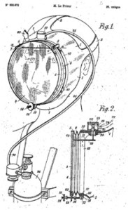
diagram of the 1946 version of the Le Prieur breathing set
There have been some cases of a single-hose-type regulator last stage built into a full-face mask so that the mask’s big front window plus the flexible rubber seal joining it to its frame, was a very big and thus very sensitive regulator diaphragm:
- Several versions of the Le Prieur breathing set. Yves Le Prieur first patented with Maurice Fernez, in 1926, a breathing apparatus using a mouthpiece, but as of 1933 he removed the mouthpiece and included a circular full-face mask in all following patents (like 1937, 1946 or 1947).
- In 1934 René Commeinhes, from Alsace (France), adapted a Rouquayrol-Denayrouze apparatus for the use of firefighters. With new 1937 and 1942 patents (GC37 and GC42) his son Georges adapted this invention to underwater breathing by means of a single hose connected to a full-face mask.
- Captain Trevor Hampton invented independently from Le Prieur a similar regulator-mask in the 1950s and submitted it for patent. The Royal Navy requisitioned the patent, but found no use for it and eventually released it. By then, the market had moved on and it was too late to make this regulator-mask in bulk for sale.
Performance of regulators
In Europe, EN250:2000 defines the minimum requirements for breathing performance of regulators.
The original Cousteau twin-hose diving regulators could deliver about 140 litres of air per minute, and that was officially thought to be adequate; but divers sometimes needed a faster rate, and had to learn not to “beat the lung”, i.e. to try to breathe faster than the regulator could supply. Between 1948 and 1952 Ted Eldred designed his Porpoise air scuba to supply 300 liters/minute if the diver need to breathe that fast, and that soon became British and Australian naval standard.
In the United States Military, scuba regulators must adhere to performance specifications as outlined by the Mil-R-24169B which was based on equipment performance until recently.
Various breathing machines have been developed and used for assessment of breathing apparatus performance. ANSTI has developed a testing machine that measures the inhalation and exhalation effort in using a regulator; publishing results of the performance of regulators in the ANSTI test machine has resulted in big performance improvements.
Manufacturers
- Air Liquide: La Spirotechnique, Apeks and Aqua Lung
- Apollo Sports
- Atomic Aquatics
- Beuchat
- Cressi-Sub
- Dive Rite
- Draeger
- HTM Sports: Dacor and Mares
- Poseidon
- ROMI Enterprises: Aeris and Oceanic
- Ocean Divers Supply
- Scubapro
- Tusa
- Zeagle
- Edge-HOG (Highly Optimized Gear)
- Swagelok Speciality Regulators {Breathing Air}
Value Added Reseller
- Dive Rite
- Coltri
- Edge-HOG
- Genesis
- Halcyon
- OMS
- Seacsub
- Sherwood
- Tigullio
- XS Scuba
Source :
PEARL

A pearl is a hard object produced within the soft tissue (specifically the mantle) of a living shelled mollusc. Just like the shell of a clam, a pearl is made up of calcium carbonate in minute crystalline form, which has been deposited in concentric layers. The ideal pearl is perfectly round and smooth, but many other shapes of pearls (baroque pearls) occur. The finest quality natural pearls have been highly valued as gemstones and objects of beauty for many centuries, and because of this, the word pearl has become a metaphor for something very rare, fine, admirable, and valuable.
The most valuable pearls occur spontaneously in the wild, but they are extremely rare. These wild pearls are referred to as natural pearls. Cultured or farmed pearls from pearl oysters and freshwater mussels make up the majority of those that are currently sold. Imitation pearls are also widely sold in inexpensive jewelry, but the quality of their iridescence is usually very poor, and often, artificial pearls are easily distinguished from genuine pearls. Pearls have been harvested and cultivated primarily for use in jewelry, but in the past they were also stitched onto lavish clothing. Pearls have also been crushed and used in cosmetics, medicines, and in paint formulations.
Whether wild or cultured, gem quality pearls are almost always nacreous and iridescent, as is the interior of the shell that produces them. However, almost all species of shelled molluscs are capable of producing pearls (formally referred to as “calcareous concretions” by some sources) of lesser shine or less spherical shape. Although these may also be legitimately referred to as “pearls” by gemological labs and also under U.S. Federal Trade Commission rules, and are formed in the same way, most of them have no value, except as curiosities.
Evolutionary significance

A pearl being extracted from an akoya pearl oyster.
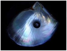
A black pearl and a shell of the black-lipped pearl oyster. The iridescent colors originate from nacre layers.
Pearls are commonly viewed by scientists as a by-product of an adaptive immune system-like function.
Etymology
The English word pearl comes from the French perle, originally from the Latin perna meaning leg, after the ham- or mutton leg-shaped bivalve.
Definition
Almost any shelled mollusk can, by natural processes, produce some kind of “pearl” when an irritating microscopic object becomes trapped within the mollusk’s mantle folds, but the great majority of these “pearls” are not valued as gemstones. Nacreous pearls, the best-known and most commercially-significant pearls, are primarily produced by two groups of molluscan bivalves or clams. A nacreous pearl is made from layers of nacre, by the same living process as is used in the secretion of the mother of pearl which lines the shell.
A “natural pearl” or “wild pearl” is one that forms without any human intervention at all, in the wild, and is very rare. Many hundreds of pearl oysters or pearl mussels have to be gathered and opened, and thus killed, to find even one wild pearl, and for many centuries that was the only way pearls were obtained. This was the main reason why pearls fetched such extraordinary prices in the past. A cultured pearl is formed in a pearl farm, using human intervention as well as natural processes.
One family of nacreous pearl bivalves – the pearl oyster – lives in the sea, while the other – a very different group of bivalves – lives in freshwater; these are the river mussels such as the freshwater pearl mussel. Saltwater pearls can grow in several species of marine pearl oysters in the family Pteriidae. Freshwater pearls grow within certain (but by no means all) species of freshwater mussels in the order Unionida, the families Unionidae and Margaritiferidae.
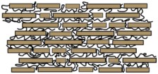
Structure of nacre layers, wherein aragonite plates are separated by biopolymers, such as chitin, lustrin and silk-like proteins
Physical properties

Electron microscopy image of a fractured surface of nacre
The unique luster of pearls depends upon the reflection, refraction, and diffraction of light from the translucent layers. The thinner and more numerous the layers in the pearl, the finer the luster. The iridescence that pearls display is caused by the overlapping of successive layers, which breaks up light falling on the surface. In addition, pearls (especially cultured freshwater pearls) can be dyed yellow, green, blue, brown, pink, purple, or black. The very best pearls have a metallic mirror-like luster.
Because pearls are made primarily of calcium carbonate, they can be dissolved in vinegar. Calcium carbonate is susceptible to even a weak acid solution because the crystals of calcium carbonate react with the acetic acid in the vinegar to form calcium acetate and carbon dioxide.
Freshwater and saltwater pearls
Freshwater and saltwater pearls may sometimes look quite similar, but they come from different sources.
Freshwater pearls form in various species of freshwater mussels, family Unionidae, which live in lakes, rivers, ponds and other bodies of fresh water. These freshwater pearl mussels occur not only in hotter climates, but also in colder more temperate areas such as Scotland (where they are totally protected under law). However, most freshwater cultured pearls sold today come from China.
Saltwater pearls grow within pearl oysters, family Pteriidae, which live in oceans. Saltwater pearl oysters are usually cultivated in protected lagoons or volcanic atolls.
Creation of a pearl
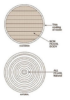
Diagram comparing a cross-section of a cultured pearl, upper, with a natural pearl, lower
The difference between wild and cultured pearls focuses on whether the pearl was created spontaneously by nature – without human intervention – or with human aid. Pearls are formed inside the shell of certain mollusks as a defense mechanism against a potentially threatening irritant such as a parasite inside its shell, or an attack from outside, injuring the mantle tissue. The mollusk creates a pearl sac to seal off the irritation.
The mantle of the mollusk deposits layers of calcium carbonate (CaCO3) in the form of the mineral aragonite or a mixture of aragonite and calcite (polymorphs with the same chemical formula, but different crystal structures) held together by an organic horn-like compound called conchiolin. The combination of aragonite and conchiolin is called nacre, which makes up mother-of-pearl. The commonly held belief that a grain of sand acts as the irritant is in fact rarely the case. Typical stimuli include organic material, parasites, or even damage that displaces mantle tissue to another part of the mollusk’s body. These small particles or organisms gain entry when the shell valves are open for feeding or respiration. In cultured pearls, the irritant is typically an introduced piece of the mantle epithelium, with or without a spherical bead (beaded or beadless cultured pearls).
Natural pearls
Natural pearls are nearly 100% calcium carbonate and conchiolin. It is thought that natural pearls form under a set of accidental conditions when a microscopic intruder or parasite enters a bivalve mollusk, and settles inside the shell. The mollusk, being irritated by the intruder, forms a pearl sac of external mantle tissue cells and secretes the calcium carbonate and conchiolin to cover the irritant. This secretion process is repeated many times, thus producing a pearl. Natural pearls come in many shapes, with perfectly round ones being comparatively rare.
Typically, the build-up of a natural pearl consists of a brown central zone formed by columnar calcium carbonate (usually calcite, sometimes columnar aragonite) and a yellowish to white outer zone consisting of nacre (tabular aragonite). In a pearl cross-section such as the diagram, these two different materials can be seen. The presence of columnar calcium carbonate rich in organic material indicates juvenile mantle tissue that formed during the early stage of pearl development. Displaced living cells with a well-defined task may continue to perform their function in their new location, often resulting in a cyst. Such displacement may occur via an injury. The fragile rim of the shell is exposed and is prone to damage and injury. Crabs, other predators and parasites such as worm larvae may produce traumatic attacks and cause injuries in which some external mantle tissue cells are disconnected from their layer. Embedded in the conjunctive tissue of the mantle, these cells may survive and form a small pocket in which they continue to secrete their natural product: calcium carbonate. The pocket is called a pearl sack, and grows with time by cell division; in this way the pearl grows also. The juvenile mantle tissue cells, according to their stage of growth, produce columnar calcium carbonate, which is secreted from the inner surface of the pearl sack. With ongoing time the external mantle cells of the pearl sack proceed to the formation of tabular aragonite. When the transition to nacre secretion occurs, the brown pebble becomes covered with a nacreous coating. As this process progresses, the shell itself grows, and the pearl sack seems to travel into the shell. However, it actually stays in its original relative position within the mantle tissue. After a couple of years, a pearl will have formed and the shell might be found by a lucky pearl fisher.
Cultured pearls

Nuclei from Toba Pearl Island, Japan
Cultured pearls are the response of the shell to a tissue implant. A tiny piece of mantle tissue from a donor shell is transplanted into a recipient shell. This graft will form a pearl sac and the tissue will precipitate calcium carbonate into this pocket. There are a number of options for producing cultured pearls: use freshwater or seawater shells, transplant the graft into the mantle or into the gonad, add a spherical bead or do it non-beaded. The majority of saltwater cultured pearls are grown with beads. The trade name of the cultured pearls are Akoya, white or golden South sea, and black Tahitian. The majority of beadless cultured pearls are mantle-grown in freshwater shells in China, known as freshwater cultured pearls.
Cultured pearls can be distinguished from natural pearls by X-ray examination. Nucleated cultured pearls are often ‘pre-formed’ as they tend to follow the shape of the implanted shell bead nucleus. Once the pre-formed beads are inserted into the oyster, it secretes a few layers of nacre around the outside surface of the implant before it is removed after six months or more.
When a cultured pearl with bead is X-rayed, it reveals a different structure to that of a natural pearl. A beaded cultured pearl shows a solid center with no concentric growth rings, whereas a natural pearl shows a series of concentric growth rings. A beadless cultured pearl (whether of freshwater or saltwater origin) may show growth rings, but also a complex central cavity, witness of the first precipitation of the young pearl sac.
Imitation pearls
Some imitation pearls are simply made of mother-of-pearl, coral or conch shell, while others are made from glass and are coated with a solution containing fish scales called essence d’Orient. Although imitation pearls look the part, they do not have the same weight or smoothness as real pearls, and their luster will also dim greatly.
Gemological identification
A well-equipped gem testing laboratory can distinguish natural pearls from cultured pearls by using gemological X-ray equipment to examine the center of a pearl. With X-rays it is possible to see the growth rings of the pearl, where the layers of calcium carbonate are separated by thin layers of conchiolin. The differentiation of natural pearls from non-beaded cultured pearls can be very difficult without the use of this X-ray technique.
Natural and cultured pearls can be distinguished from imitation pearls using a microscope. Another method of testing for imitations is to rub two pearls against each other. Imitation pearls are completely smooth, but natural and cultured pearls are composed of nacre platelets, making both feel slightly gritty.
Value of a natural pearl
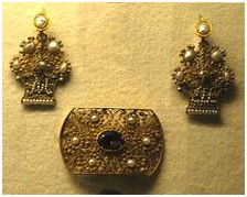
A brooch and a set of earrings from the 19th century made from gold and natural pearls
Quality natural pearls are very rare jewels. The actual value of a natural pearl is determined in the same way as it would be for other “precious” gems. The valuation factors include size, shape, color, quality of surface, orient and luster.
Single, natural pearls are often sold as a collector’s item, or set as centerpieces in unique jewelry. Very few matched strands of natural pearls exist, and those that do often sell for hundreds of thousands of dollars. (In 1917, jeweler Pierre Cartier purchased the Fifth Avenue mansion that is now the New York Cartier store in exchange for a matched, double strand of natural pearls that he had been collecting for years; valued at the time at $1 million USD.)
The Great Depression effectively slashed the value of the natural pearl, but there is no doubt that it had been some time coming. The introduction and advance of the cultured pearl hit the pearl industry hard; it had pearl dealers publicly disputing over the authenticity of these new cultured pearls, and left many consumers uneasy and confused about the much lower prices. Essentially, it damaged the image of both natural and cultured pearls alike. By the 1950s, an era of every woman being able to own her own pearl necklace had begun, and natural pearls were reduced to a small, exclusive niche in the pearl industry.
Origin of a natural pearl
Previously, natural pearls were found in many parts of the world. Present day natural pearling is confined mostly to seas off Bahrain. Australia also has one of the world’s last remaining fleets of pearl diving ships. Australian pearl divers dive for south sea pearl oysters to be used in the cultured south sea pearl industry. The catch of pearl oysters is similar to the numbers of oysters taken during the natural pearl days. Hence significant numbers of natural pearls are still found in the Australian Indian Ocean waters from wild oysters. X-ray examination is required to positively verify natural pearls found today.
Types of cultured pearls
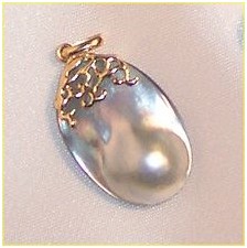
A blister pearl, a half-sphere, formed flush against the shell of the pearl oyster.
Keshi pearls, although they often occur by chance, are not considered natural pearls. They are a byproduct of the culturing process, and hence do not happen without human intervention. These pearls are quite small: typically a few millimeters in size. Keshi pearls are produced by many different types of marine mollusks and freshwater mussels in China. Keshi pearls are actually a mistake in the cultured pearl seeding process. In seeding the cultured pearl, a piece of mantle muscle from a sacrificed oyster is placed with a bead of mother of pearl within the oyster. If the piece of mantle should slip off the bead, a pearl forms of baroque shape about the mantle piece which is entirely nacre. Therefore, a Keshi pearl could be considered superior to cultured pearls with a mother of pearl bead center. In the cultured pearl industry, the resources used to create a mistaken all nacre baroque pearl is a drain on the production of round cultured pearls. Therefore, they are trying to improve culturing technique so that keshi pearls do not occur. All nacre pearls may one day be limited to natural found pearls. Today many “keshi” pearls are actually intentional, with post-harvest shells returned to the water to regenerate a pearl in the existing pearl sac.
Tahitian pearls, frequently referred to as black pearls, are highly valued because of their rarity; the culturing process for them dictates a smaller volume output and they can never be mass produced because, in common with most sea pearls, the oyster can only be nucleated with one pearl at a time, while freshwater mussels are capable of multiple pearl implants. Before the days of cultured pearls, black pearls were rare and highly valued for the simple reason that white pearl oysters rarely produced naturally black pearls, and black pearl oysters rarely produced any natural pearls at all.

Mary, Queen of Scots by an unknown artist after François Clouet (c. 1559)
London, Victoria and Albert Museum
London, Victoria and Albert Museum
The Queen is shown wearing her rope of famous black pearls.
Since the development of pearl culture technology, the black pearl oyster found in Tahiti and many other Pacific Island areas has been extensively used for producing cultured pearls. The rarity of the black cultured pearl is now a “comparative” issue. The black cultured pearl is rare when compared to Chinese freshwater cultured pearls, and Japanese and Chinese akoya cultured pearls, and is more valuable than these pearls. However, it is more abundant than the South Sea pearl, which is more valuable than the black cultured pearl. This is simply because the black pearl oyster Pinctada margaritifera is far more abundant than the elusive, rare, and larger south sea pearl oyster Pinctada maxima, which cannot be found in lagoons, but which must be dove for in a rare number of deep ocean habitats or grown in hatcheries.
Black pearls are very rarely black: they are usually shades of green, purple, aubergine, blue, grey, silver or peacock (a mix of several shades, like a peacock’s feather).
Black cultured pearls from the black pearl oyster – Pinctada margaritifera – are not South Sea pearls, although they are often mistakenly described as black South Sea pearls. In the absence of an official definition for the pearl from the black oyster, these pearls are usually referred to as “black pearls”.
The correct definition of a South Sea pearl – as described by CIBJO and GIA – is a pearl produced by the Pinctada maxima pearl oyster. South Sea pearls are the color of their host Pinctada maxima oyster – and can be white, silver, pink, gold, cream, and any combination of these basic colors, including overtones of the various colors of the rainbow displayed in the pearl nacre of the oyster shell itself.
South Sea pearls are produced in various parts of the world. White ones tend to come from the Broome area of Australia while golden ones are from the Philippines. Pearls are also produced in the Cook Islands and one farm in the Sea of Cortez, Mexico, from Concha Nácar the rainbow lipped oyster; these pearls fluoresce red under ultraviolet light.
Pearls from other species

A shell of the Indian volute, Melo melo, surrounded by a number of pearls from this species
Biologically speaking, under the right set of circumstances, almost any shelled mollusk can produce some kind of pearl, however, most of these molluscan pearls have no luster or iridescence. The great majority of mollusk species produce pearls which are not attractive, and are sometimes not even very durable, such that they usually have no value at all, except perhaps to a scientist, a collector, or as a curiosity. These objects used to be referred to as “calcareous concretions” by some gemologists, even though a malacologist would still consider them to be pearls. Valueless pearls of this type are sometimes found in edible mussels, edible oysters, escargot snails, and so on. The GIA and CIBJO now simply use the term ‘pearl’ (or, where appropriate, the more descriptive term ‘non-nacreous pearl’) when referring to such items and, under Federal Trade Commission rules, various mollusc pearls may be referred to as ‘pearls’, without qualification.
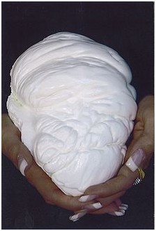
Pearl of Lao Tzu, the largest known pearl came from a giant clam
A few species produce pearls that can be of interest as gemstones. These species include the bailer shell Melo, the giant clam Tridacna, various scallop species, Pen shells Pinna, and the Haliotis iris species of abalone. Abalone, or Pāua are Mabe pearls unique to New Zealand waters and are commonly referred to as ‘Blue Pearls’. They are admired for their incredible luster and naturally bright vibrant colors that are often compared to Opal. Another example is the conch pearl (sometimes referred to simply as the ‘pink pearl’), which is found very rarely growing between the mantle and the shell of the queen conch or pink conch, Strombus gigas, a large sea snail or marine gastropod from the Caribbean Sea. These pearls, which are often pink in color, are a by-product of the conch fishing industry, and the best of them display a shimmering optical effect related to chatoyance known as ‘flame structure’. In 1999, the world auction record for a Melo pearl was US$488,311 for a single pearl.
Somewhat similar gastropod pearls, this time more orange in hue, are (again very rarely) found in the horse conch Pleuroploca gigantea.
The largest pearl known was found in the Philippines in 1934 and is known as the Pearl of Lao Tzu. It is a naturally-occurring, non-nacreous, calcareous concretion (pearl) from a giant clam. Because it did not grow in a pearl oyster it is not pearly; instead the surface is glossy like porcelain. Other pearls from giant clams are known to exist, but this is a particularly large one, weighing 14 lb (6.4 kg).
History
Pearl hunting

A 14th-century piece of clothing used by Kuwaiti divers searching for pearls in the Arabian Sea
For thousands of years, most seawater pearls were retrieved by divers working in the Indian Ocean, in areas like the Persian Gulf, the Red Sea, and in the Gulf of Mannar. Starting in the Han Dynasty (206 BC–220 AD), the Chinese hunted extensively for seawater pearls in the South China Sea. In the 14th-century Arabian Sea, the traveller Ibn Battuta provided the earliest known description of pearl diving by means of attaching a cord to the diver’s waist.

Catching of pearls, Bern Physiologus (9th century)
When Spanish conquistadors arrived in the Western Hemisphere, they discovered that around the islands of Cubagua and Margarita, some 200 km north of the Venezuelan coast, was an extensive pearl bed (a bed of pearl oysters). One discovered and named pearl, La Peregrina pearl, was offered to the Spanish queen. According to Garcilasso de la Vega, who says that he saw La Peregrina at Seville in 1607, (Garcilasso, “Historie des Incas, Rois du Perou,” Amsterdam, 1704, Vol. II, P. 352.) this was found at Panama in 1560 by a slave worker who was rewarded with his liberty, and his owner with the office of alcalde of Panama.
Margarita pearls are extremely difficult to find today and are known for their unique yellowish color. The most famous Margarita necklace that any one can see today is the one that then Venezuelan President Romulo Betancourt gave to Jacqueline Kennedy when she and her husband, President John F. Kennedy paid an official visit to Venezuela.
Before the beginning of the 20th century, pearl hunting was the most common way of harvesting pearls. Divers manually pulled oysters from ocean floors and river bottoms and checked them individually for pearls. Not all mussels and oysters produce pearls. In a haul of three tons, only three or four oysters will produce perfect pearls.
Pearl farming
Today, the cultured pearls on the market can be divided into two categories. The first category covers the beaded cultured pearls, including Akoya, South Sea and Tahiti. These pearls are gonad grown, and usually one pearl is grown at a time. This limits the number of pearls at a harvest period. The pearls are usually harvested after one year for akoya, 2–4 years for Tahitian and South Sea, and 2–7 years for freshwater. This perliculture process was first developed by the British biologist William Saville-Kent who passed the information along to Tatsuhei Mise and Tokichi Nishikawa from Japan. The second category includes the non-beaded freshwater cultured pearls, like the Biwa or Chinese pearls. As they grow in the mantle, where on each wing up to 25 grafts can be implanted, these pearls are much more frequent and saturate the market completely. An impressive improvement in quality has taken place in the last ten years when the former rice grain-shaped pebbles are compared with the near round pearls of today. In the last two years large near perfect round bead nucleated pearls up to 15mm in diameter have been produced with metallic luster.
The nucleus bead in a beaded cultured pearl is generally a polished sphere made from freshwater mussel shell. Along with a small piece of mantle tissue from another mollusk (donor shell) to serve as a catalyst for the pearl sac, it is surgically implanted into the gonad (reproductive organ) of a saltwater mollusk. In freshwater perliculture, only the piece of tissue is used in most cases, and is inserted into the fleshy mantle of the host mussel. South Sea and Tahitian pearl oysters, also known as Pinctada maxima and Pinctada margaritifera, which survive the subsequent surgery to remove the finished pearl, are often implanted with a new, larger beads as part of the same procedure and then returned to the water for another 2–3 years of growth.
Despite the common misperception, Mikimoto did not discover the process of pearl culture. The accepted process of pearl culture was developed by the British Biologist William Saville-Kent in Australia and brought to Japan by Tokichi Nishikawa and Tatsuhei Mise. Nishikawa was granted the patent in 1916, and married the daughter of Mikimoto. Mikimoto was able to use Nishikawa’s technology. After the patent was granted in 1916, the technology was immediately commercially applied to akoya pearl oysters in Japan in 1916. Mise’s brother was the first to produce a commercial crop of pearls in the akoya oyster. Mitsubishi’s Baron Iwasaki immediately applied the technology to the south sea pearl oyster in 1917 in the Philippines, and later in Buton, and Palau. Mitsubishi was the first to produce a cultured south sea pearl – although it was not until 1928 that the first small commercial crop of pearls was successfully produced.
The original Japanese cultured pearls, known as akoya pearls, are produced by a species of small pearl oyster, Pinctada fucata martensii, which is no bigger than 6 to 8 cm in size, hence akoya pearls larger than 10 mm in diameter are extremely rare and highly priced. Today, a hybrid mollusk is used in both Japan and China in the production of akoya pearls.
Recent pearl production
In 2010, China overtook Japan in akoya pearl production. Japan has all but ceased its production of akoya pearls smaller than 8 mm. Japan maintains its status as a pearl processing center, however, and imports the majority of Chinese akoya pearl production. These pearls are then processed (often simply matched and sorted), relabeled as product of Japan, and exported.
In the past two decades, cultured pearls have been produced using larger oysters in the south Pacific and Indian Ocean. The largest pearl oyster is the Pinctada maxima, which is roughly the size of a dinner plate. South Sea pearls are characterized by their large size and warm luster. Sizes up to 14 mm in diameter are not uncommon. South Sea pearls are primarily produced in Australia, Indonesia, and the Philippines.
Mitsubishi commenced pearl culture with the south sea pearl oyster in 1916, as soon as the technology patent was commercialized. By 1931 this project was showing signs of success, but was upset by the death of Tatsuhei Mise. Although the project was recommenced after Tatsuhei’s death, the project was discontinued at the beginning of WWII before significant productions of pearls were achieved.
After WWII, new south sea pearl projects were commenced in the early 1950s in Burma and Kuri Bay and Port Essington in Australia. Japanese companies were involved in all projects using technicians from the original Mitsubishi south sea pre-war projects.
Freshwater pearl farming
In 1914, pearl farmers began growing cultured freshwater pearls using the pearl mussels native to Lake Biwa. This lake, the largest and most ancient in Japan, lies near the city of Kyoto. The extensive and successful use of the Biwa Pearl Mussel is reflected in the name Biwa pearls, a phrase which was at one time nearly synonymous with freshwater pearls in general. Since the time of peak production in 1971, when Biwa pearl farmers produced six tons of cultured pearls, pollution has caused the virtual extinction of the industry. Japanese pearl farmers recently cultured a hybrid pearl mussel – a cross between Biwa Pearl Mussels and a closely related species from China, Hyriopsis cumingi, in Lake Kasumigaura. This industry has also nearly ceased production, due to pollution.
Japanese pearl producers also invested in producing cultured pearls with freshwater mussels in the region of Shanghai, China. China has since become the world’s largest producer of freshwater pearls, producing more than 1,500 metric tons per year (in addition to metric measurements, Japanese units of measurement such as the kan and momme are sometimes encountered in the pearl industry).
Led by pearl pioneer John Latendresse and his wife Chessy, the United States began farming cultured freshwater pearls in the mid 1960s. National Geographic magazine introduced the American cultured pearl as a commercial product in their August 1985 issue. The Tennessee pearl farm has emerged as a tourist destination in recent years, but commercial production of freshwater pearls has ceased.
Momme Weight
For many cultured pearl dealers and wholesalers, the preferred weight measure used for loose pearls and pearl strands is momme. Momme is a weight measure used by the Japanese for centuries. Today, momme weight is still the standard unit of measure used by most pearl dealers to communicate with pearl producers and wholesalers. One momme corresponds to 1/1000 kan. Reluctant to give up tradition, in 1891, the Japanese government formalized the kan measure as being exactly 1 kan = 3.75 kilograms or 8.28 pounds. Hence, 1 momme = 3.75 grams or 3750 milligrams.
In the United States, during the 19th and 20th centuries, through trade with Japan in silk cloth the momme became a unit indicating the quality of silk cloth.
Though millimeter size range is typically the first factor in determining a cultured pearl necklace’s value, the momme weight of pearl necklace will allow the buyer to quickly determine if the necklace is properly proportioned. This is especially true when comparing the larger south sea and Tahitian pearl necklaces.
Pearls in jewelry
Ring of Tahitian pearl
The value of the pearls in jewelry is determined by a combination of the luster, color, size, lack of surface flaw and symmetry that are appropriate for the type of pearl under consideration. Among those attributes, luster is the most important differentiator of pearl quality according to jewelers.
All factors being equal, however, the larger the pearl the more valuable it is. Large, perfectly round pearls are rare and highly valued. Teardrop-shaped pearls are often used in pendants.
Shapes
Pearls come in eight basic shapes: round, semi-round, button, drop, pear, oval, baroque, and circled. Perfectly round pearls are the rarest and most valuable shape. Semi-rounds are also used in necklaces or in pieces where the shape of the pearl can be disguised to look like it is a perfectly round pearl. Button pearls are like a slightly flattened round pearl and can also make a necklace, but are more often used in single pendants or earrings where the back half of the pearl is covered, making it look like a larger, rounder pearl.

Portrait of Empress Maria Fiodorovna in a Head-Dress Decorated with Pearls by Ivan Kramskoi (1880s)
Saint Petersburg, Hermitage Museum
Saint Petersburg, Hermitage Museum
Drop and pear shaped pearls are sometimes referred to as teardrop pearls and are most often seen in earrings, pendants, or as a center pearl in a necklace. Baroque pearls have a different appeal; they are often highly irregular with unique and interesting shapes. They are also commonly seen in necklaces. Circled pearls are characterized by concentric ridges, or rings, around the body of the pearl.
In general, cultured pearls are less valuable than natural pearls, whereas imitation pearls almost have no value. One way that jewelers can determine whether a pearl is cultured or natural is to have a gemlab perform an X-ray examination of the pearl. If X-rays reveals a nucleus, the pearl is likely a bead-nucleated saltwater pearl. If no nucleus is present, but irregular and small dark inner spots indicating a cavity are visible, combined with concentric rings of organic substance, the pearl is likely a cultured freshwater. Cultured freshwater pearls can often be confused for natural pearls which present as homogeneous pictures which continuously darken toward the surface of the pearl. Natural pearls will often show larger cavities where organic matter has dried out and decomposed.
Lengths of pearl necklaces

Portrait of Caterina Sagredo Barbarigo by Rosalba Carriera, cir. 1740. The subject is wearing a single-strand pearl collar and pendant pearl earrings

Queen of Italy, Margherita of Savoy, owned one of the most famous collections of natural pearls. She is wearing a multi-strand choker and a rope of pearls, possibly with matching bracelet and earrings
There is a special vocabulary used to describe the length of pearl necklaces. While most other necklaces are simply referred to by their physical measurement, pearl necklaces are named by how low they hang when worn around the neck. A collar, measuring 10 to 13 inches or 25 to 33 cm in length, sits directly against the throat and does not hang down the neck at all; collars are often made up of multiple strands of pearls. Pearl chokers, measuring 14 to 16 inches or 35 to 41 cm in length, nestle just at the base of the neck. A strand called a princess length, measuring 17 to 19 inches or 43 to 48 cm in length, comes down to or just below the collarbone. A matinee length, measuring 20 to 24 inches or 50 to 60 cm in length, falls just above the breasts. An opera length, measuring 28 to 35 inches or 70 to 90 cm in length, will be long enough to reach the breastbone or sternum of the wearer; and longer still, a pearl rope, measuring more than 45 inches or 115 cm in length, is any length that falls down farther than an opera.
Necklaces can also be classified as uniform, or graduated. In a uniform strand of pearls, all pearls are classified as the same size, but actually fall in a range. A uniform strand of akoya pearls, for example, will measure within 0.5 mm. So a strand will never be 7 mm, but will be 6.5–7 mm. Freshwater pearls, Tahitian pearls, and South Sea pearls all measure to a full millimeter when considered uniform.
A graduated strand of pearls most often has at least 3 mm of differentiation from the ends to the center of the necklace. Popularized in the United States during the 1950s by the GIs bringing strands of cultured akoya pearls home from Japan, a 3.5 momme, 3 mm to 7 mm graduated strand was much more affordable than a uniform strand because most of the pearls were small.
Colors of pearl jewelry
Earrings and necklaces can also be classified on the grade of the color of the pearl. While white, and more recently black, saltwater pearls are by far the most popular, other color tints can be found on pearls from the oceans. Pink, blue, champagne, green, black and even purple saltwater pearls can be encountered, but to collect enough of these rare colors to form a complete string of the same size and same shade can take years.
Religious references
Hindu scriptures
The Hindu tradition describes the sacred Nine Pearls which were first documented in the Garuda Purana, one of the books of the Hindu mythology. Ayurveda contains references to pearl powder as a stimulant of digestion and to treat mental ailments. According to Marco Polo, the kings of Malabar wore a necklace of 104 rubies and pearls which was given from one generation of kings to the next. The reason was that every king had to say 104 prayers every morning and every evening. At least until the beginning of the 20th century it was a Hindu custom to present a completely new, undrilled pearl and pierce it during the wedding ceremony.
The Pearl or Mukta in Sanskrit is also associated with many Hindu deities. The most famous being the Koustubha which Lord Vishnu wears on his chest. Apart from religious connotations, stories and folklore abound of pearls occurring in snakes, the Naaga Mani, and elephants, the Gaja Mukta.
Hebrew scriptures
According to Rebbenu Bachya, the word Yahalom in the verse Exodus 28:18 means “pearl” and was the stone on the Hoshen representing the tribe of Zebulun. This is generally disputed among scholars, particularly since the word in question in most manuscripts is actually Yasepheh – the word from which jasper derives; scholars think that refers to green jasper (the rarest and most prized form in early times) rather than red jasper (the most common form). Yahalom is usually translated by the Septuagint as an “onyx”, but sometimes as “beryl” or as “jasper”; onyx only started being mined after the Septuagint was written, so the Septuagint’s term “onyx” probably does not mean onyx – onyx is originally an Assyrian word meaning ring, and so could refer to anything used for making rings. Yahalom is similar to a Hebrew word meaning hit hard, so some people think that it means diamond. The variation in possibilities of meaning for this sixth stone in the Hoshen is reflected in different translations of the Bible – the King James Version translates the sixth stone as diamond, the New International Version translates it as emerald, and the Vulgate translates it as jaspis – meaning jasper. There is a wide range of views among traditional sources about which tribe the stone refers to.
New Testament scriptures
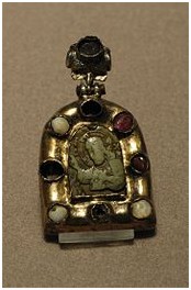
Religious pendant showing Christ blessing, framed with rubies and pearls, from the Byzantine empire, 12th or 13th century
In a Christian New Testament parable, Jesus compared the Kingdom of Heaven to a “pearl of great price” in Matthew 13: 45–46. “Again, the kingdom of heaven is like unto a merchant man, seeking goodly (fine) pearls: Who, when he had found one pearl of great price, went and sold all that he had, and bought it.”
The twelve gates of the New Jerusalem are reportedly each made of a single pearl in Revelation 21:21, that is, the Pearly Gates. “And the twelve gates were twelve pearls; every gate was of one pearl: and the streets of the city were pure gold, as if transparent glass.”
Holy things are compared to pearls in Matthew 7:6. “Do not give dogs what is holy, and do not throw your pearls before pigs, lest they trample them underfoot and turn to attack you.”
Pearls are also found in numerous references showing the wickedness and pride of a people, as in Revelation 18:16. “And saying, Alas, alas, that great city, that was clothed in fine linen, in purple and scarlet, and decked with gold, and precious stones, and pearls!”
Islamic scriptures
The Qur’an often mentions that dwellers of paradise will be adorned with pearls:
22:23 God will admit those who believe and work righteous deeds, to Gardens beneath which rivers flow: they shall be adorned therein with bracelets of gold and pearls; and their garments there will be of silk.
35:33 Gardens of Eternity will they enter: therein will they be adorned with bracelets of gold and pearls; and their garments there will be of silk.
52:24 Round about them will serve, [devoted] to them, youths [handsome] as pearls well-guarded.
Other scriptures
The metaphor of a pearl appears in the longer Hymn of the Pearl, a poem respected for its high literary quality, and use of layered theological metaphor, found within one of the texts of Gnosticism.
The Pearl of Great Price is a book of scripture in The Church of Jesus Christ of Latter-day Saints.
Source :
DIVING CYLINDER
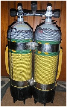
A diving cylinder, scuba tank or diving tank is a gas cylinder used to store and transport high pressure breathing gas as a component of a scuba set. It provides gas to the scuba diver through the demand valve of a diving regulator.
Diving cylinders typically have an internal volume of between 3 and 18 litres (0.11 and 0.64 cu ft) and a maximum pressure rating from 200 to 300 bars (2,900 to 4,400 psi). The internal cylinder volume is also expressed as “water capacity” – the volume of water which could be contained by the cylinder. When pressurised, a cylinder carries a volume of gas greater than its water capacity because gas is compressible. 600 litres (21 cu ft) of gas at atmospheric pressure is compressed into a 3-litre cylinder when it is filled to 200 bar. Cylinders also come in smaller sizes, such as 0.2, 1.5 and 2 litres, however these are not generally used for breathing, instead being used for purposes such as Surface Marker Buoy, drysuit and buoyancy compensator inflation.
Divers use gas cylinders above water for many purposes including storage of gases for oxygen first aid treatment of diving disorders and as part of storage “banks” for diving air compressor stations. They are also used for many purposes not connected to diving. For these applications they are not diving cylinders.
The term “diving cylinder” tends to be used by gas equipment engineers, manufacturers, support professionals, and divers speaking British English. “Scuba tank” or “diving tank” is more often used colloquially by non-professionals and native speakers of American English. The term “oxygen tank” is commonly used by non-divers when referring to diving cylinders; however, this is a misnomer. These cylinders typically contain (atmospheric) breathing air, or an oxygen-enriched air mix. They rarely contain pure oxygen, except when used for rebreather diving, shallow decompression stops in technical diving or for in-water oxygen recompression therapy. Breathing oxygen at depths greater than 20 feet (6.1 m)(equivalent to a partial pressure of oxygen of 1.6 ATA) can result in oxygen toxicity, a highly dangerous condition that can trigger seizures and thus lead to drowning.
Parts of a cylinder
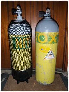
A steel 15l cylinder with net and boot and a bare 12l aluminium cylinder
Two 12l steel cylinders connected by an isolation manifold and tank bands
The diving cylinder consists of several parts:
The pressure vessel
The pressure vessel is normally made of cold-extruded aluminium or forged steel. An especially common cylinder available at tropical dive resorts is an “aluminium-80” which is an aluminium cylinder with an internal volume of 0.39 cubic feet (11 L) rated to hold about 80 cubic feet (2,300 L) of atmospheric pressure gas at its rated pressure of 3,000 psi (210 bar). Aluminium cylinders are also often used where divers carry many cylinders, such as in technical diving in warm water where the dive suit does not provide much buoyancy, because the greater buoyancy of aluminium cylinders reduces the extra buoyancy the diver would need to achieve neutral buoyancy. They are also preferred when carried as “sidemount” or “sling” cylinders as the near neutral buoyancy allows them to hang comfortably along the sides of the diver’s body, without disturbing trim, and can be handed off to another diver with a minimal effect on buoyancy. In cold water diving, where a diver wearing a highly buoyant thermally insulating dive suit has a large excess of buoyancy, steel cylinders are often used because they are denser than aluminium cylinders. Kevlar wrapped composite cylinders are used in fire fighting breathing apparatus and oxygen first aid equipment, but are rarely used for diving, due to their high positive buoyancy.
The aluminium alloys used for diving cylinders are 6061 and 6351. 6351 alloy is subject to sustained stress cracking and cylinders manufactured of this alloy should be periodically eddy current tested according to national legislation and manufacturer’s recommendations.
The neck of the cylinder is internally threaded to fit a cylinder valve. There are several standards for neck threads, these include:
- Taper thread (17E), with a 12% taper right hand thread, standard Whitworth 55° form with a pitch of 14 threads per inch and pitch diameter at the top thread of the cylinder of 18.036mm. These connections are sealed using thread tape and torqued to between 120 and 150 N.m on steel cylinders, and 75 to 140 N.m on aluminium cylinders
Parallel threads are made to several standards:
- M25x2 parallel thread, which is sealed by an O-ring and torqued to 100 to 130 N.m on steel, and 95 to 130 N.m on aluminium cylinders
- M18x1.5 parallel thread, which is sealed by an O-ring, and torqued to 100 to 130 N.m on steel cylinders, and 85 to 100 N.m on aluminium cylinders
- 3/4″x14 BSP parallel thread. This has a 55° Whitworth thread form, a pitch diameter of 25.279mm and a pitch of 14 threads per inch (1,814mm)
- 3/4″x14 NGS (NPSM)parallel thread, sealed by an O-ring, torqued to 40 to 50 ft.lbf on aluminium cylinders This has a 60° thread form, a pitch diameter of 0.9820″ to 0.9873″, and a pitch of 14 threads per inch.
- 3/4″x16 UNF, sealed by an O-ring, torqued to 40 to 50 ft.lbf on aluminium cylinders
The 3/4″NGS and 3/4″BSP are very similar, whaving the same pitch and a pitch diameter that only differs by about 0.2mm, but they are not compatible, as the thread forms are different.
All taper thread valves are sealed using an O-ring at top of the neck thread which seals in a chamfer or step in the cylinder neck and against the flange of the valve.
The shoulder of the cylinder carries stamp markings providing required information about the cylinder
Stamp markings on an American manufacture aluminum 40 cu.ft. 3000 psi cylinder
Stamp markings on an American manufacture aluminum 80 cu.ft. 3000 psi cylinder
Stamp markings on an Italian manufacture steel 6 l 300 bar cylinder
The cylinder valve
- the pillar valve or cylinder valve is the point at which the pressure vessel connects to the diving regulator. The purpose of the pillar valve is to control gas flow to and from the pressure vessel and to form a seal with the regulator. Some countries require that the pillar valve includes a burst disk, a type of pressure ‘fuse’, that will fail before the pressure vessel fails in the event of overpressurization.
- a rubber o-ring forms a seal between the metal of the pillar valve and the metal of the diving regulator. Fluoroelastomer (i.e. “viton”) o-rings are used with cylinders storing oxygen-rich gas mixtures to reduce the risk of fire.
Types of cylinder valve
Cylinder valves are classified by three basic aspects: The connection with the cylinder, the connection to the regulator, and other distinguishing features.
Cylinder thread variations
Cylinder threads are in two basic configurations: Taper thread and parallel thread. The thread specification must match the neck thread of the cylinder.
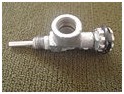
Draeger 300 bar taper thread DIN cylinder valve
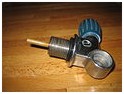
A 232 bar DIN connection cylinder valve with parallel thread cylinder connection
Connection to the regulator
There are three types of cylinder valve in general use for Scuba cylinders containing air:
- A-clamp or yoke – the connection on the regulator surrounds the valve pillar and presses the output O-ring of the pillar valve against the input seat of the regulator. The yoke is screwed down snug by hand (overtightening can make the yoke impossible to remove later without tools) and the seal is created by pressure when the valve is opened. This type is simple, cheap and very widely used worldwide. It has a maximum pressure rating of 232 bar and the weakest part of the seal, the O-ring, is not well protected from overpressurisation.
- 232 bar DIN (5-thread, G5/8) – the regulator screws into the cylinder valve trapping the O-ring securely. These are more reliable than A-clamps because the O-ring is well protected, but many countries do not use DIN fittings widely on compressors, or cylinders which have DIN fittings, so a European diver with a DIN system abroad in many places will need to take an adaptor.
- 300 bar DIN (7-thread, G5/8) – these are similar to 5-thread DIN fitting but are rated to 300 bar working pressures. The 300 bar pressures are common in European diving and in US cave diving, but their acceptance in U.S. sport diving has been hampered by the fact that United States Department of Transportation rules presently prohibit the transport of metal scuba cylinders on public roads with pressures above about 230 bar, even if the cylinders and air delivery systems have been rated for these pressures by the American agencies which oversee cylinder testing and equipment compatibility for SCUBA (Occupational Safety and Health Administration and Compressed Gas Association).
Pressure rating
DIN valves are produced in 200 bar and 300 bar pressure ratings. The number of threads and the detail configuration of the connections is designed to prevent incompatible combinations of filler attachment or regulator attachment with the cylinder valve.
Yoke valves are rated between 200 and 240 bar, and there does not appear to be any mechanical design detail preventing connection between any yoke fittings, though some older yoke clamps will not fit over the popular 232/240 bar combination DIN/yoke cylinder valve as the yoke is too narrow.
Adaptors are available to allow connection of DIN regulators to yoke cylinder valves (A-clamp or yoke adaptor), and to connect yoke regulators to DIN cylinder valves. (plug adaptors and block adaptors) Plug adaptors are rated for 232/240 bar. Block adaptors are generally rated for 200 bar.
There are also cylinder valves for Scuba cylinders containing gases other than air:
- The new European Norm EN 144-3:2003 introduced a new type of valve, similar to existing 232 bar or 300 bar DIN valves, however, with a metric M 26×2 fitting on both the cylinder and the regulator. These are to be used for breathing gas with oxygen content above that normally found in natural air in the Earth’s atmosphere (i.e. 22–100%). From August 2008, these shall be required for all diving equipment used with nitrox or pure oxygen. The idea behind this new standard is to prevent a rich mixture being filled to a cylinder that is not oxygen clean. However even with use of the new system there still remains nothing except human procedural care to ensure that a cylinder with a new valve remains oxygen-clean – which is exactly how the current system works.
- A male thread cylinder valve was supplied with some Dräger semi-closed circuit recreational rebreathers (Dräger Ray) for use with nitrox mixtures.
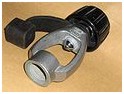
A yoke (A-clamp) to DIN adaptor allows connection of a DIN regulator to a Yoke cylinder valve
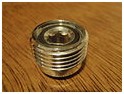
Din plug adaptor
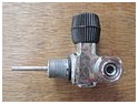
DIN valve with plug adaptor for yoke attachment fitted
Other distinguishing features
Plain valves
- The most commonly used cylinder valve type is the single outlet plain valve, sometimes known as a “K” valve, which allows connection of a single regulator, and has no reserve function. It simply opens to allow gas flow, or closes to shut it off. Several configurations are used, with options of DIN or A-clamp connection, and vertical or transverse spindle arrangements. The valve is operated by turning a knob, usually rubber or plastic, which affords a comfortable grip. Several turns are required to fully open the valves. Some DIN valves are convertible to A-clamp by use of an insert which is screwed into the opening.
- Y and H cylinder valves have two outlets, each with its own valve, allowing two regulators to be connected to the cylinder. If one regulator “freeflows”, which is a common failure mode, or ices up, which can happen in water below about 5°C, its valve can be closed and the cylinder breathed from the regulator connected to the other valve. The difference between an H valve and a Y valve is that the Y valve body splits into two posts roughly 90° to each other and 45° from the vertical axis, looking like a Y, while an H valve is usually assembled from a valve designed as part of a manifold system with an additional valve post connected to the manifold socket, with the valve posts parallel and vertical, which looks a bit like an H. Y-valves are aso known as “slingshot valves” due to their appearance.
Reserve valves
- Reserve lever or “J-valve” (obsolescent). Until the 1970s, when submersible pressure gauges on regulators came into common use, diving cylinders often used a mechanical reserve mechanism to indicate to the diver that the cylinder was nearly empty. The gas supply was automatically cut-off when the gas pressure reached the reserve pressure. To release the reserve, the diver pulled down on a rod that ran along the side of the cylinder and which activated a lever on the valve. The diver would then finish the dive before the reserve (typically 300 pounds per square inch (21 bar)) was consumed. On occasion, divers would inadvertently trigger the mechanism while donning gear or performing a movement underwater and, not realizing that the reserve had already been accessed, could find themselves out of air at depth with no warning whatsoever. The J-valve got its name from being item number J in one of the first scuba equipment manufacturer catalogs. The standard non-reserve yoke valve at the time was item K, and is often still referred to as a K-valve. J-valves are still occasionally used by professional divers in zero visibility, where the SPG can not be read.
- Less common in the 1950s thru 1970s was an R-valve which was equipped with a restriction that caused breathing to become difficult as the cylinder neared exhaustion, but that would allow less restricted breathing if the diver began to ascend and the ambient water pressure lessened, providing a larger pressure differential over the orifice. It was never particularly popular because, were it necessary for the diver to descend (as is often necessary in cave and wreck diving, breathing would become progressively more difficult as the diver went deeper, eventually becoming impossible until the diver could begin his or her ascent.
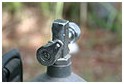
A “J” valve from c.1960

Draeger taper thread cylinder valve with reserve lever

“H”-valve with DIN connections
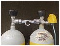
Draeger 200 bar cylinder valves with manifold and reserve lever
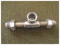
Draeger 200 bar cylinder manifold
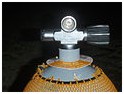
Left side cylinder valve for barrel seal manifold with blanking plug and DIN connection
Accessories
Additional components for convenience, protection or other functions, not directly required for the function as a pressure vessel.
Manifolds
A cylinder manifold is a tube which connects two cylinders together so that the contents of both can be supplied to one or more regulators. There are three commonly used configurations of manifold:
- The earliest type is a tube with a connector on each end which is attached to the cylinder valve outlet, and an outlet connection in the middle, to which the regulator is attached. A variation on this pattern includes a reserve valve at the outlet connector. The cylinders are isolated from the manifold when closed, and the manifold can be attached or disconnected while the cylinders are pressurised.
- More recently, manifolds have become available which connect the cylinders on the cylinder side of the valve, leaving the outlet connection of the cylinder valve available for connection of a regulator. This means that the connection cannot be made or broken while the cylinders are pressurised, as there is no valve to isolate the manifold from the interior of the cylinder. This apparent inconvenience allows a regulator to be connected to each cylinder, and isolated from the internal pressure independently, which allows a malfunctioning regulator on one cylinder to be isolated while still allowing the regulator on the other cylinder access to all the gas in both cylinders.
- These manifolds may be plain or may include an isolation valve in the manifold, which allows the contents of the cylinders to be isolated from each other. This allows the contents of one cylinder to be isolated and secured for the diver if a leak at the cylinder neck thread, manifold connection, or burst disk on the other cylinder causes its contents to be lost.
A relatively uncommon manifold system is a connection which screws directly into the neck threads of both cylinders, and has a single valve to release gas to a connector for a regulator. These manifolds can include a reserve valve, either in the main valve or at one cylinder. This system is mainly of historical interest.
Cylinder bands
Cylinder bands are straps, usually of stainless steel, which are used to clamp two cylinders together as a twin set. The cylinders may be manifolded or independent. It is usual to use a cylinder band near the top of the cylinder, just below the shoulders, and one lower down. The standard distance between centrelines for bolting to a backplate is 11 inches (280 mm).
Cylinder boot
A cylinder boot is a hard rubber or plastic cover which fits over the base of a diving cylinder to protect the paint from abrasion and impact, to protect the surface the cylinder stands on from impact with the cylinder, and in the case of round bottomed cylinders, to allow the cylinder to stand upright on its base.
Cylinder net
A cylinder net is a tubular net which is stretched over a cylinder and tied on at top and bottom. The function is to protect the paintwork from scratching, and on booted cylinders it also helps drain the surface between the boot and cylinder, which reduces corrosion problems under the boot. Mesh size is usually about 6 millimetres (0.24 in). Some divers will not use boots or nets as they can snag more easily than a bare cylinder and constitute an entrapment hazard in some environments such as caves and the interior of wrecks.
Cylinder handle
A cylinder handle may be fitted, usually clamped to the neck, to conveniently carry the cylinder. This can also increase the risk of snagging in an enclosed environment.
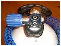
A 15 litre, 232 bar cylinder with “Yoke” valve and cylinder handle

A 12 litre, 232 bar cylinder with DIN valve. The colour coding is the old UK standard for air prior to 2006
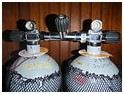
Face sealed isolation manifold on twin 12 l steel cylinders. The plastic discs are records of the latest internal inspection
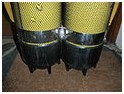
Twinned cylinders showing cylinder boots and lower band
Cylinder capacity

12 litre and 3 litre steel diving cylinders: Typical Primary and Pony sizes
There are two commonly used conventions for describing the capacity of a diving cylinder. One is based on the internal volume of the cylinder. The other is based on nominal volume of gas stored.
Internal volume
The internal volume is commonly quoted in most countries. It can be measured easily by filling the cylinder with fresh water. This has resulted in the term ‘water capacity’ (WC) which is often marked on the cylinder shoulder. It’s almost always expressed as a volume but sometimes as weight of the water. Fresh water has a density close to one kilogram per litre so the numerical values will be similar.
The usual units are:
- Volume in litres
- Weight in kilograms
- Pressure in bar.
Nominal volume of gas stored
The nominal volume of gas stored is commonly quoted in the USA. It’s a measure of the volume of gas that can be released from the cylinder at atmospheric pressure. Terms used for the volume include ‘free gas’ or ‘free gas equivalent’. It depends on the internal volume and the working pressure of a cylinder. If the working pressure is higher, the cylinder will store more gas for the same volume.
The working pressure is not necessarily the same as the actual pressure used. Some cylinders are permitted to exceed the nominal working pressure by 10% and this is indicated by a ‘+’ symbol. This extra pressure allowance is dependant on the cylinder passing the appropriate periodical hydrostatic test and is not generally valid for US cylinders exported to countries with differing standards.
For example, common Al80 cylinder is an aluminum cylinder which has a nominal ‘free gas’ volume of 80 cubic feet (2,300 L) when pressurised to 3,000 pounds per square inch (210 bar). It has an internal volume of 10.94 litres (0.386 cu ft).
Applications and configurations of diving cylinders
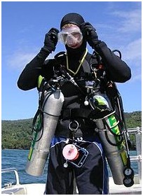
Technical diver with decompression gases in side mounted stage cylinders.
Divers may carry one cylinder or multiples, depending on the requirements of the dive. Where diving takes place in low risk areas, where the diver may safely make a free ascent, or where a buddy is available to provide an alternative air supply in an emergency, recreational divers usually carry only one cylinder. An example of this type is coral reef diving where it is possible to do an interesting dive without going deep or needing decompression. Where diving risks are higher, for example where the visibility is low or when recreational divers do deeper or decompression diving, divers routinely carry more than one gas source. An example of this type is north European diving where the temperature is often less than 15 °C (60 °F) and visibility less than 10 m (33 ft) and many interesting dive sites are shipwrecks in deeper water on the sea bed.
Diving cylinders may serve different purposes. One or two cylinders may be used as a primary breathing source which is intended to be breathed from for most of the dive. A smaller cylinder carried in addition to a larger cylinder is called a “pony bottle”. A cylinder to be used purely as an independent safety reserve is called a “bailout bottle”. A pony bottle is commonly used as a bailout bottle, but this would depend on the time required to surface.
Divers doing technical diving often carry different gases, each in a separate cylinder, for each phase of the dive:
- “travel gas” is used during the descent and ascent. It is typically air or nitrox with an oxygen content between 21% and 40%. Travel gas is needed when the bottom gas is hypoxic and therefore is unsafe to breathe in shallow water.
- “bottom gas” is only breathed at depth. It is typically a helium-based gas which is low in oxygen (below 21%) or hypoxic (below 17%).
- “deco gas” is used at the decompression stops and is generally a nitrox with a high oxygen content, or pure oxygen, to accelerate decompression.
- a “stage” is a cylinder holding reserve, travel or deco gas. They are usually carried “side slung”, clipped on either side of the diver to the harness of the backplate and wing or buoyancy compensator, rather than on the back. Commonly divers use aluminium stage cylinders because they are nearly neutrally buoyant in water and can be removed underwater with less effect on the diver’s overall buoyancy.
Rebreathers may use internal cylinders:
- oxygen rebreathers have an oxygen cylinder
- semi-closed circuit rebreathers have a cylinder which usually contains nitrox or a helium based gas.
- closed circuit rebreathers have an oxygen cylinder and a “diluent” cylinder, which contains air, nitrox or a helium based gas
Rebreathers may also be supplied from “off-board” cylinders, which are not permanently plumbed into the rebreather, but connected to it by a flexible hose and coupling and usually carried side slung. Rebreather divers also often carry a bailout cylinder if the internal diluent cylinder is too small for safe use for bailout.
For safety, divers sometimes carry an additional independent scuba cylinder with its own regulator to mitigate out-of-air emergencies should the primary breathing gas supply fail. For much common recreational diving where a controlled emergency swimming ascent is acceptably safe, this extra equipment is not needed or used. This extra cylinder is known as a bail-out cylinder, and may be carried in several ways, and can be any size that can hold enough gas to get the diver safely back to the surface.
Open-circuit
For open-circuit divers, there are several options for the combined cylinder and regulator system:
- Single cylinder or single aqualung: consists of a single large cylinder with one first-stage regulator, and usually two secondary regulator/mouthpieces. This configuration is simple and cheap but it is only a single system: it has no redundancy in case of failure. If the cylinder or first-stage regulator fails, the diver is totally out of air and faces an emergency. All training agencies train divers to rely on a buddy to assist them in this situation. The skill of gas sharing is required at the most basic scuba course. This equipment configuration, although common with entry-level divers and for most sport diving, is not recommended for any dive that is deeper than 30 m (100 ft) or where decompression stops are needed, or where there is an overhead environment (wreck diving, cave diving, or ice diving). Generally, these conditions, because they prevent immediate emergency ascent, may define technical diving.
- Single cylinder with dual regulators: consists of a single large cylinder with two first-stage regulators, each with a second stage regulator/mouthpiece. This system is used for recreational diving where cold water makes redundancy required. It is common in continental Europe, especially Germany. The advantage is that a regulator failure can be solved underwater to bring the dive to a controlled conclusion without buddy breathing or gas sharing. However, it is hard to reach the valves, so there is some reliance on the dive buddy to help close the valves of the free-flowing regulator quickly.
- Main cylinder plus a small independent cylinder: this configuration uses a larger, main cylinder along with an independent smaller cylinder, often called a “pony”. The diver has two independent systems, but the total ‘breathing system’ is now heavier, more expensive to buy and maintain.
- The pony is typically a 2 to 5 litre cylinder. Its capacity determines the depth of dive and decompression duration for which it provides protection. Ponies are generally fixed to the diver’s buoyancy compensator (BC) or main cylinder behind the diver’s back. They can also be clipped to the BC at the diver’s side or chest. Ponies provided an acceptable emergency supply but are only useful if the diver trains to bail out, i.e. to use one.
- Another type of separate small air source is a hand-held cylinder filled with about 85 litres (0.279 ft) of free air with a diving regulator directly attached, such as the Spare Air. This source provides only a few breaths of gas at depth and is mainly suitable as a shallow water bailout.
- Independent twin set /doubles: this consists of two independent cylinders and two regulators. This system is heavier, more expensive to buy and maintain and more expensive to fill. Also the diver must swap demand valves during dive to preserve a safety reserve of air in each cylinder. If this is not done, then should a cylinder fail the diver may end up having no reserve. Independent twin sets do not work well with air-integrated computers – as they usually only monitor one cylinder. Many divers feel the complexity of switching regulators periodically to ensure both cylinders are evenly used is offset by the redundancy of two entirely separate breathing supplies. These will normally be mounted as a twin set on the diver’s back, but alternatively can be carried in a sidemount configuration where penetration of wrecks or caves requires it.
- Manifolded twin set /doubles with a single regulator: two cylinders are joined at their pillar valves with a manifold but only one regulator is attached to the system. This makes it simple and cheap but means there is no redundant breathing system, only a double gas supply.
- Manifolded twin set /doubles with two regulators: consist of two cylinders with their pillar valves joined with a manifold, with a valve that can isolate the two pillar valves. In the event of a problem with one cylinder the diver may close the isolator valve to preserve gas in the cylinder which has not failed. The pros of this configuration include a large gas supply, no requirement to change regulators underwater, automatic gas supply management, and in most failure situations the diver may close a failed valve or isolate a cylinder in order to leave himself with an emergency supply. On the down side the manifold is another potential point of failure, and there is a danger of losing all air if the manifold valve cannot be closed when a problem occurs. This configuration of cylinders is often used in Technical diving.
- Sling bottles/cylinders: are a configuration of independent cylinder used for technical diving. They are independent cylinders with their own regulators and are carried clipped to the harness at the side of the diver. Their purpose may be to carry either stage, travel, decompression, or bailout gas while the back mounted cylinder(s) carry bottom gas. Stage cylinders carry gas to extend bottom time, travel gas is used to reach a depth where bottom gas may be safely used if it is hypoxic at the surface, and decompression gas is gas intended to be used during decompression to accelerate the elimination of inert gases. Bailout gas is an emergency supply intended to be used to surface if the main gas supply is lost.
- Side mount cylinders: are sling cylinders mounted at the diver’s side which carry bottom gas when the diver does not carry back mount cylinders. They may be used in conjunction with other sling cylinders where necessary.
Closed-circuit
Diving cylinders are used in closed-circuit diving in two roles:
- As part of the rebreather itself. The rebreather must have at least one source of fresh gas stored in a cylinder; many have two and some have more cylinders. Due to the lower gas consumption of rebreathers, these cylinders typically are smaller than those used for equivalent open-circuit dives. See the main article: rebreather.
- In a bail out system: rebreather divers often carry one or more redundant gas sources should the rebreather fail:
- Open-circuit: a simple diving cylinder and regulator. The number of open-circuit bail outs, their capacity and the breathing gases they contain depend on the depth and decompression needs of the dive. So on a deep, technical rebreather dive, the diver will need a bail out “bottom” gas and a bail out “decompression” gas for use. On such a dive, it is the capacity and duration of the bail out that limits the depth and duration of the dive – not the capacity of the rebreather.
- Closed-circuit: a rebreather containing a diving cylinder and regulator. Using another rebreather as a bail out is possible but uncommon. Although the long duration of rebreathers seems compelling for a bail out, rebreathers are relatively bulky, complex, vulnerable to damage and require more time to start breathing from, than easy-to-use, instantly available, robust and reliable open-circuit equipment.
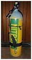
Long 9.2 litre aluminium cylinder rigged for sling mounting

15 litre, 232 bar, A clamp single cylinder open circuit breathing set

7 litre, 232 bar, DIN pillar valve independent twin set. The left cylinder shows manufacturer markings. The right cylinder shows test stamps

Manifolded twin 12 litre, 232 bar breathing set with two A-clamp pillar valves and two regulators
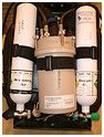
Two 3 litre, 232 bar, DIN cylinders inside an Inspiration Diving Rebreather closed circuit breathing set.
Gas calculations
Breathing gas endurance
A commonly asked question is ‘what is the underwater duration of a particular cylinder?’
There are two parts to this problem:
The cylinder’s capacity to store gas
Two features of the cylinder determine its gas carrying capacity:
- working gas pressure : this normally ranges between 200 and 300 bars (2,900 and 4,400 psi)
- internal volume : this normally ranges between 3 litres and 18 litres
To calculate the quantity of gas:
Volume of gas at atmospheric pressure = (cylinder volume) x (cylinder pressure) / (atmospheric pressure)
So a 12 litre cylinder at 232 bar would hold almost 2,784 litres (98.3 cu ft) of air at atmospheric pressure.
In the US and in many diving resorts you might find aluminum cylinders with an internal capacity of 0.39 cubic feet (11 L) filled to 3,000 psi (210 bar); Taking air pressure as 14.7 psi, this gives 0.39 x 3000 / 14.7 = 80 ft³ These cylinders would be described by US convention as “80 cubic foot cylinders”, (the common “aluminum-80”) as the US normally refers to cylinder capacity as free-air equivalent at its working pressure, rather than the internal volume of the cylinder, which is the measure commonly used in metric countries.
Up to 200 bar the ideal gas law remains valid and the relationship between the pressure, size of the cylinder and gas contained in the cylinder is linear; at higher pressures there is proportionally less gas in the cylinder. A 3 litre, 300 bar cylinder can only carry up to 810 litres (29 cu ft) of atmospheric pressure gas and not the 900 litres expected from the ideal gas law.
Diver gas consumption
There are three factors at work here:
- breathing rate or respiratory minute volume (RMV) of the diver. In normal conditions this will be between 10 and 25 litres per minute (L/min) for recreational divers who are not working hard. At times of extreme high work rate, breathing rates can rise to 95 L/min. In the UK, a working breathing rate of 40 litres per minute is used for commercial diving, whilst a figure of 50 litres per minute is used for emergencies. (The Association of Diving Contractors)
- time
- ambient pressure: the depth of the dive determines this. The ambient pressure at the surface is 1 bar (15 psi). For every 10 metres (33 ft) in salt water the diver descends, the pressure increases by 1 bar (15 psi). As a diver goes deeper, the breathing gas is delivered at a pressure equal to ambient water pressure. Thus, it requires twice as much mass of gas to fill the same volume (the diver’s lungs) at 10 metres (33 ft) as it does at the surface, and three times as much at 20 metres (66 ft). If a given cylinder consumed at a constant rate would last a diver one hour at the surface, it would last 30 minutes at 10 metres (33 ft), 20 minutes at 20 metres (66 ft) and just 15 minutes at 30 metres (98 ft).
To calculate the quantity of gas consumed:
gas consumed = breathing rate × time × ambient pressure
Thus, a diver with a breathing rate of 20 L/min will consume at 30 meters (4 bar) the equivalent of 80 L/min at 1 bar (e.g. at the surface). If this diver only had a 10 litre 200 bar cylinder to breathe from, the gas in the cylinder would be exhausted after 2000/80 = 25 minutes.
Keeping this in mind, it is not hard to see why technical divers who do long deep dives require multiple cylinders or rebreathers.
Breathing time
For metric users:
Absolute maximum breathing time (BT) can be calculated as
BT = available air / rate of consumption
which, using the ideal gas law, is
BT = (available cylinder pressure × cylinder volume) / (rate of air consumption at surface) × (ambient pressure)
This may be written as
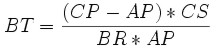
(1)
with
BT = Breathing Time (in minutes)
CP = Cylinder Pressure (in bars)
CS = Cylinder Size (in liters)
AP = Ambient Pressure (in bars)
BR = Breathing Rate (in liters per minute)
AP is deducted from CP, as the quantity of air represented by AP can in practice not be used for breathing by the diver as she needs it to overcome the pressure of the water (AP) when inhaling.
However, in normal diving usage, a reserve is always factored in. The reserve is a proportion of the cylinder pressure which a diver will not expect to use other than in case of emergency. The reserve may be a quarter or a third of the cylinder pressure or it may be a fixed pressure, common examples are 50 bar and 500 psi. The formula above is then modified to give the usable breathing time as

(2)
where RP is the reserve pressure.
Ambient pressure (AP) is the surrounding water pressure at a given depth and is made up of the sum of the water pressure and the air pressure at the surface. It is calculated as
(3)

+ atmospheric pressure
with
D = Depth (in meters)
g = Standard gravity (in meters per second squared)
ρ = Water Density (in kg per cube meter)
In practical terms, this formula can be approximated by
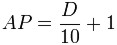
(4)
For example (using the first formula (1) for absolute maximum breathing time), a diver at a depth of 15 meters in water with an average density of 1020 kg / m³ (typical salt water), who breathes at a rate of 20 liters per minute, using a dive cylinder of 18 liters pressurized at 200 bars, can breathe for a period of 72 minutes before the cylinder and supply line pressure has fallen so low as to prevent her from inhaling. In most open circuit scuba systems this happens quite suddenly, from a normal breath to the next abnormal breath, a breath which typically cannot be fully drawn. (There is never any difficulty exhaling). In such circumstances there remains air under pressure in the cylinder, but the diver is unable to breathe it. Some of it can be breathed if the diver ascends, and even without ascent, in some systems a bit of air from the cylinder is available to inflate BCD devices even after it no longer has pressure enough to actuate the mouthpiece valve.
Using the same conditions and a reserve of 50 bar, the formula (2) for usable breathing time is worked thus:
Ambient pressure = water pressure + atmospheric pressure = 15/10 + 1 = 2.5 bar
Usable air = usable pressure * cylinder capacity = (200-50) * 18 = 2700 liters
Rate of consumption = surface air consumption * ambient pressure = 20 * 2.5 = 50 liters/min
Usable breathing time = 2700 liters / 50 liters/min = 54 min
This would give a dive time of 54 min at 15 m before reaching the reserve of 50 bar.
Reserves
It is strongly recommended that a portion of the usable gas of the cylinder be held aside as a safety reserve. The reserve is designed to provide gas for longer than planned decompression stops or to provide time to resolve underwater emergencies.
The size of the reserve depends upon the risks involved during the dive. A deep or decompression dive warrants a greater reserve than a shallow or a no stop dive. In recreational diving for example, it is recommended that the diver plans to surface with a reserve remaining in the cylinder of 500 psi, 50 bar or 25% of the initial capacity, depending of the teaching of the diver training organisation. This is because recreational divers practicing within “no-decompression” limits can normally make a direct ascent in an emergency. On technical dives where a direct ascent is either impossible (due to overhead obstructions) or dangerous (due to the requirement to make decompression stops), divers plan larger margins of safety using the rule of thirds: one third of the gas supply is planned for the outward journey, one third is for the return journey and one third is a safety reserve.
Some training agencies teach the concept of minimum gas and provide a simple calculation that allows a diver to work out an acceptable reserve to get two divers in an emergency to the surface. See DIR diving for more information.
Weight of gas consumed
The loss of the weight of the gas taken from the cylinder makes the cylinder and diver more buoyant. This can be a problem if the diver is unable to remain neutrally buoyant towards the end of the dive because most of the gas has been breathed from the cylinder.
Table showing the buoyancy of diving cylinders in water when empty and full of air.
Assumes 1 litre of air at atmospheric pressure and 10°C weighs 1.25g.
|
Cylinder
|
Air
|
Weight on land
|
Buoyancy
|
|||||
|
Material
|
Volume
|
Pressure
|
Volume
|
Weight
|
Empty
|
Full
|
Empty
|
Full
|
|
(litre)
|
(bar)
|
(litre)
|
(kg)
|
(kg)
|
(kg)
|
(kg)
|
(kg)
|
|
|
Steel
|
12
|
200
|
2400
|
3.0
|
16.0
|
19.0
|
-1.2
|
-4.3
|
|
15
|
200
|
3000
|
3.8
|
20.0
|
23.8
|
-1.4
|
-5.2
|
|
|
16 (XS 130)
|
230
|
3680
|
4.7
|
19.5
|
23.9
|
-0.9
|
-5.3
|
|
|
2×7
|
200
|
2800
|
3.5
|
19.5
|
23.0
|
-2.0
|
-5.6
|
|
|
8
|
300
|
2400
|
3.0
|
13.0
|
16.0
|
-3.5
|
-6.5
|
|
|
10
|
300
|
3000
|
3.8
|
17.0
|
20.8
|
-4.0
|
-7.8
|
|
|
2×4
|
300
|
2400
|
3.0
|
15.0
|
18.0
|
-4.0
|
-7.0
|
|
|
2×6
|
300
|
3600
|
4.6
|
21.0
|
25.6
|
-5.0
|
-9.6
|
|
|
Aluminium
|
9 (AL 63)
|
203
|
1826
|
2.3
|
12.2
|
13.5
|
+1.8
|
-0.5
|
|
11 (AL 80)
|
203
|
2247
|
2.8
|
14.4
|
17.2
|
+1.8
|
-1.1
|
|
|
13 (AL100)
|
203
|
2584
|
3.2
|
17.1
|
20.3
|
+1.4
|
-1.7
|
|
Filling cylinders
Diving cylinders should only be filled with air from diving air compressors or with other breathing gases using gas blending techniques. Both these services should be provided by reliable suppliers such as dive shops. Breathing industrial compressed gases can be lethal because the high pressure increases the effect of any impurities in them.
Special precautions need to be taken with gases other than air:
- oxygen in high concentrations is a major cause of fire and rust.
- oxygen should be very carefully transferred from one cylinder to another and only ever stored in containers that are certified and labeled for oxygen use.
- gas mixtures containing proportions of oxygen other than 21% could be extremely dangerous to divers who are unaware of the proportion of oxygen in them. All cylinders should be labeled with their composition.
- cylinders containing a high oxygen content must be cleaned for the use of oxygen and lubricated with oxygen service grease to reduce the chance of combustion.
Contaminated air at depth can be fatal. Common contaminants are: carbon monoxide a by-product of combustion, carbon dioxide a product of metabolism, oil and lubricants from the compressor.
Keeping the cylinder slightly pressurized at all times reduces the possibility of contaminating the inside of the cylinder with corrosive agents, such as sea water, or toxic material, such as oils, poisonous gases, fungi or bacteria.
The blast caused by a sudden release of the gas pressure inside a diving cylinder makes them very dangerous if mismanaged. The greatest risk of explosion exists at filling time and comes from thinning of the walls of the pressure vessel due to corrosion. Another cause of failure is damage or corrosion of the threads and neck of the cylinder where the pillar valve is screwed in. Aluminium cylinders have been observed occasionally to fail explosively, fragmenting the cylinder wall. Steel cylinders usually remain mostly intact, and tend to fail at the neck.
Manufacture and testing
Most countries require diving cylinders to be checked on a regular basis, see gas cylinder. This usually consists of an internal visual inspection and a hydrostatic test.
- In the United States, a visual inspection is NOT required by the USA DOT every year though they do require a hydrostatic every five years. The visual inspection requirement is a diving industry standard based on observations made during a review by the National Underwater Accident Data Center.
- In European Union countries a visual inspection is required every 2.5 years, and a hydrostatic every five years.
- In Norway a hydrostatic (including a visual inspection) is required 3 years after production date, then every 2 years.
- Legislation in Australia requires that cylinders are hydrostatically tested every twelve months, regardless.
- In South Africa a hydrostatic test is required every 4 years, and visual inspection every year. Eddy current testing of neck threads must be done according to the manufacturer’s recommendations.
A hydrostatic test involves pressurising the cylinder to its test pressure (often 5/3 or 3/2 of the working pressure) and measuring its volume before and after the test. A permanent increase in volume above the tolerated level means the cylinder fails the test and is permanently removed from service.
When a cylinder is manufactured, its specification, including Working Pressure, Test Pressure, Data of Manufacture, Capacity and Weight are stamped on the cylinder.
After a cylinder passes the test, the test date, (or the test expiry date in some countries such as Germany), is punched into the shoulder of the cylinder for easy verification at fill time. Note: this is a European requirement. There is an international standard for the stamp format
Most compressor operators check these details before filling the cylinder and may refuse to fill non-standard or out-of-test cylinders. Note: this is a European requirement, a requirement of the USA DOT, and a South African requirement.
Safety
Before any cylinder is filled, verification of testing dates and a visual examination for external damage and corrosion are required by law in some jurisdictions, and are prudent even if not legally required at other places. In the United States, scuba tanks must be hydro-tested every five years and visually inspected every year. Test dates can be checked by looking at the visual inspection sticker and the hydro-test date is stamped on top of the cylinder.
Before use the user should verify the contents of the cylinder and check the function of the cylinder valve. Pressure and gas mixture are critical information for the diver, and the valve should open freely without sticking or leaks from the spindle seals. Sniffing air bled from a cylinder may also reveal unpleasant surprises better left on land than discovered in the water.
Cylinders should not be left standing unattended unless secured so that they can not fall in reasonable foreseeable circumstances as an impact could damage the cylinder valve mechanism, and cocievably fracture the valve at the neck threads. This is more likely with taper thread valves, and when it happens the energy of the compressed gas is released within a second, and can accelerate the cylinder to speeds which can causes severe injury or damage to the surroundings.
A neatly assembled setup, with regulators, gauges, and delicate computers butterflied inside the BCD, or clipped where they will not be walked on, and stowed under the boat bench or secured to a rack, is the practice of a competent diver.
As the scuba set is a life support system, one should not touch a fellow diver’s gear, even to move it, without their knowledge and approval.
Full cylinders should not be exposed to temperatures above 65°C and cylinders should not be filled to pressures greater than the developed pressure appropriate to the certified working pressure of the cylinder except by a test station performing a hydrostatic test.
Cylinders should be clearly labelled with their current contents. A generic “Nitrox” or “Trimix” label will alert the user that the contents may not be air, and must be analysed before use. In some parts of the world a label is required specifically indicating that the contents are air, and in other places a colour code without additional labels indicates by default that the contents are air.
Cases of lateral epicondylitis are also reported from the handling of diving cylinders.
Gas cylinder colour coding and labeling
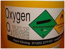
A contents label for oxygen usage (UK)
European Union
In the European Union gas cylinders may be colour coded according to EN 1098-3. The “shoulder” is the top of the cylinder close to the pillar valve. For mixed gases, the colours can be either bands or “quarters”.
- Air has either a white (RAL 9010) top and black (RAL 9005) band on the shoulder, or white (RAL 9010) and black (RAL 9005) “quartered” shoulders.
- Heliox has either a white (RAL 9010) top and brown (RAL 8008) band on the shoulder, or white (RAL 9010) and brown (RAL 8008) “quartered” shoulders.
- Nitrox, like Air, has either a white (RAL 9010) top and black (RAL 9005) band on the shoulder, or white (RAL 9010) and black (RAL 9005) “quartered” shoulders.
- Pure oxygen has a white shoulder (RAL 9010).
- Pure helium has a brown shoulder (RAL 9008).
- Trimix has a white, black and brown segmented shoulder.
Note: As of the end of 2006, the quartered parts is obsolete, and new cylinders are now with the band, and the old system is repainted.
In the European Union breathing gas cylinders must be labeled with their contents. The label should state the type of breathing gas contained by the cylinder.
South Africa
Scuba cylinders are required to comply with the colours and markings specified in SANS 10019:2006.
- Cylinder colour is Golden yellow with a French grey shoulder.
- Cylinders containing gases other than air or medical oxygen must have a transparent adhesive label stuck on below the shoulder with the word NITROX or TRIMIX in green and the composition of the gas listed.
- Cylinders containing medical oxygen must be black with a white shoulder.
In many recreational diving settings where air and nitrox are the widely used gases, nitrox cylinders are colour-coded with a green stripe on yellow bottom. The normal colour of aluminium diving cylinders is their natural silver. Steel diving cylinders are often painted, to reduce corrosion, mainly yellow or white to increase visibility. In some industrial cylinder identification colour tables, yellow shoulders means chlorine and more generally within Europe it refers to cylinders with Toxic and/or Corrosive contents; but this is of no significance in SCUBA since gas fittings would not be compatible.
Cylinders that are subject to gas blending with pure oxygen also need an “oxygen service certificate” label indicating they have been prepared for use in an oxygen-rich environment.
<!– amazon_ad_tag="pacicorn-20"; amazon_ad_width="468"; amazon_ad_height="60"; amazon_color_background="000000"; amazon_color_border="43EDD1"; amazon_color_logo="010320"; amazon_color_text="06F90E"; amazon_color_link="F9081F"; amazon_ad_logo="hide"; amazon_ad_link_target="new"; amazon_ad_border="hide"; amazon_ad_title="Diving Equipment"; //–>
Source :
RELATED TOPICS
SWIMFINS
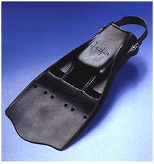
Swimfins, swim fins, fins or flippers are worn on the foot or leg and made from finlike rubber or plastic, to aid movement through the water in water sports activities such as swimming, bodyboarding, bodysurfing, kneeboarding, riverboarding, and various types of underwater diving.
Scuba divers use fins to move through water efficiently, as human feet being very small provide relatively poor thrust, especially when the diver is carrying equipment that increases hydrodynamic drag. Very long fins and monofins are used by freedivers as a means of underwater propulsion that does not require high frequency leg movement.
History
Early inventors, including Leonardo da Vinci and Giovanni Alfonso Borelli, toyed with the concept of swimfins.
Benjamin Franklin made a pair of early swimfins when he was a young boy living in Boston, Massachusetts near the Charles River; they were two thin pieces of wood, about the shape of an art palette, which allowed him to move faster than he usually did in the water.
Modern swimfins are an invention from the Frenchman Louis de Corlieu, capitaine de corvette (Lieutenant Commander) in the French Navy. In 1914 De Corlieu made a practical demonstration of his first prototype for a group of navy officers, Yves le Prieur among them who, years later in 1926, invented an early model of scuba set. De Corlieu left the French Navy in 1924 to fully devote himself to his invention. In April 1933 he registered a patent (number 767013, which in addition to two fins for the feet included two spoon-shaped fins for the hands) and called this equipment propulseurs de natation et de sauvetage (which can be translated literally as “swimming and rescue propulsion device”).
After floundering for years, even producing his fins in his own flat in Paris, De Corlieu finally started mass production of his invention in France in 1939. The same year he issued a licence to Owen P. Churchill for mass production in the United States. To sell his fins in the USA Owen Churchill changed the French De Corlieu’s name (propulseurs) to “swimfins”, which is still the common English name. Churchill presented his fins to the US Navy, which decided to acquire them for its Underwater Demolition Team (UDT). American UDT and British COPP frogmen (COPP: Combined Operations Pilotage Parties) used the “Churchill fins” during all prior underwater deminings, thus enabling in 1944 the Normandy landings. During the years after World War II had ended, De Corlieu spent time and efforts struggling in civil procedures, suing others for patent infringement.
In Britain, Dunlop made frogman’s fins for World War II, but after the war saw no market for them in peacetime, and, after the first supply of war-surplus frogman’s kit was used up, the British public had no access to swimfins (except for home-made attempts such as gluing marine plywood to plimsolls), until Oscar Gugen began importing swimfins and swimming goggles from France.
In 1946 Lillywhites imported about 1100 pairs of swimfins; they all sold in under 3 months.
In 1948 Luigi Ferraro, collaborating with the Italian diving equipment company Cressi-sub, designed the first full-foot fin, the Rondine, named after the Italian word for swallow. A distinctive feature of Cressi’s continuing Rondine full-foot fin line is the embossed outline of the bird on the foot pockets and the blades.
In 1949 Ivor Howitt or a friend of his mailed to the Dunlop Rubber Company for swimfins; Dunlop answered that they had no plans to make swimfins and saw no use for them in peacetime. Howitt made his own swimfins with innertube rubber stretched across a frame of stiff rubber tube.
Types
 Cressi-sub vented paddle fin
 Beuchat Closed-heel Jetfins
Beuchat Open-heel adjustable Jetfins
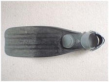 Long bladed open heel fin with moderately stiff plastic blade
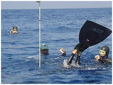 A freediver using a monofin
|
Types of fins have evolved to address the unique requirements of each community using them. Scuba divers, in particular, need large wide fins to overcome the water resistance caused by their diving equipment; snorkelers need lightweight flexible fins; ocean swimmers, bodysurfers, and lifeguards favor smaller designs that stay on their feet when moving through large surf and that make walking on the beach less awkward. In general there are two main groups of fins; full foot and open heel. Full foot fins fit like a shoe, and are designed to be worn over bare feet. If a larger size is chosen, however, full-foot fins can also be worn over socks and thin-soled booties. They are commonly used for surface swimming, and are in non adjustable sizes. Open heel have a foot pocket with an open heel area, and the fin is held to the foot by springs or straps. They can be worn over boots, and are common in diving. Many companies design fins with the same fin architecture but a choice of heel type. Other, more specific design trends are listed below.
Common types
Paddle fins
These are the most basic fins; a pair of simple stiff plastic, composite, or rubber blades that work as extensions of the feet while kicking. Some paddle fins have channels and grooves to improve power and efficiency though it has been shown that the desired effect does not occur. Paddle fins are widely believed to be the most versatile and have improved swimming economy in men. Tests in women showed a more flexible fin to be more economical, most likely due to lower leg power.
Vented fins
Vented fins were first designed in 1964 by Georges Beuchat and commercialised as Jetfins. The Jetfin tradename and design were sold to Scubapro in the 1970s. This style of fin is strongly favored by technical divers that use a frog kick allowing a high degree of control but sacrifice speed for low oxygen consumption. Vented fins are generally stiff paddle fins that have vents at the base of the foot pocket. The vents are intended to allow for the passage of water during the recovery stroke, but prevent passage during power strokes due to the blade angle, attempting to lessen effort during recovery and improve kick efficiency. A review and study by Pendergast et al in 2003 concluded that vented fins did not improve economy, implying that water does not pass through the vents. There is a risk of objects catching in the vents.
Split fins
Some swimfins have the end of the blade split. The manufacturers claim that split fins operate similarly to a propeller, by creating lift forces to move the swimmer forwards. The claim is that water flowing toward the center of the fin’s “paddle” portion also gains speed as it focuses, creating a “suction” force. A 2003 study by Pendergast et al called this into question by showing that there was no significant change in performance for a particular split fin design when the split was taped over. The technology used in most commercial split fin designs is patented by the industrial design firm Nature’s Wing, and is used under license.
Freediving fins
These are very similar to paddle fins, except they are far longer, and designed to work with slow stiff-legged kicks that claims to conserve energy. The vast majority are made in the “full-foot” design with very rigid footpockets, which serves to reduce weight and maximize power transfer from the leg into the fin. Freediving fins are commonly made of plastic, but are also often made from materials such as fiberglass and carbon fiber.
Monofins
A monofin is typically used in finswimming and free-diving. It consists of a single surface attached to footpockets for both the free-diver’s feet. Monofins can be made of glass fibre or carbon fibre. The diver’s muscle power and swimming style, and the type of activity the monofin is used for, determine the choice of size, stiffness, and materials.
Less usual types
Open and closed heel fins are predominant, but there is a range of fins that have specialised blade attachment architecture. These include (these names are tradenames):
Delfins
The Mor-Fin Corporation produces “delfins”, which are swimfins that end short and to the end is attached a shape like a fish’s forked homocercal caudal fin. The entire fin is based on the anatomy of various marine animals.
Force fins
“Force Fin” is the trademark for fins designed, developed, manufactured and distributed by Bob Evans Designs, Inc. They are distinguished by an open foot pocket, that encloses only the instep, leaving the toes free so the foot can flex.
Shinfins
These fins are attached to the ankle and rest against the (anatomically) upper side of the foot. The manufacturers claim this avoids leg cramps and reduces foot strain.
Flipfins

Flipfins in use by frogmen attacking in a harbor, for better mobility on land
Flipfins are an open-heel swimfin designed to allow easy walking on land. Its blade and foot part are separate: the blade hinges onto the foot part at each side, roughly on the level of the metatarsal heads, and when swimming is held in line by a clip on the front of the foot part. On land or when wading the blade can be unclipped and hinged vertically so it does not interfere with walking.
Breast stroke fins
Breast stroke fins are optimized for use with the breaststroke.
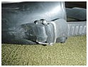
Swim fin strap attacment with simple rubber strap and wire buckle

Swim fin strap attachment with swivelling plastic buckle and clip
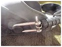
Aftermarket stainless steel spring fin strap attached with long D-shackles for security
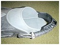
Open heel fin with stainless steel spring strap with rubber padding
Training
Divers are initially taught to fin with legs straight, without excess bending of the knee, the action coming from the hips; a leg action with much knee bending like riding a bicycle is inefficient and is a common fault with divers who have not learned properly how to fin swim. Fins with differing characteristics (e.g. stiffness) may be preferred, depending on the application, and divers may have to learn a modified finning style to match.
The upper limit of a diver’s fin-kick thrust force using a stationary-swimming ergometer was shown to be 64 newtons (14 lbf). The maximum thrust averaged over 20 seconds against a strain gauge has been measured as high as 192 newtons (43 lbf). Resistive respiratory muscle training improves and maintains endurance fin swimming performance in divers.
MORE SWIMFINS


Source :
